Replacing the seal, Remove the motor and bearing assembly, Determine the seal type – Bell & Gossett P76966E Booster Pumps 11/2HP User Manual
Page 5: Disconnect the electrical supply, Pump body diagram, Seal series 2, Seal series pd38, pd40, Rotation, Priming and starting
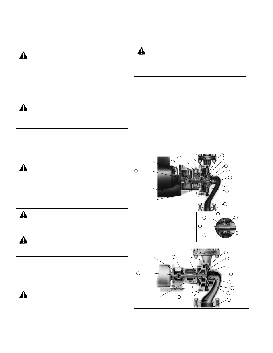
DETERMINE THE SEAL TYPE
Cut away diagrams have been provided to illustrate the compo-
nents of the booster bearing assemblies. The primary feature
distinguishing the mechanical seals of the 2
1
/
2
", LD3, HD3,
PD35, and PD37 pumps from the PD38 and PD40 is the shape
of the spring retainer which is seated between the spring and
the impeller. Refer to the following diagrams whenever seal
replacement becomes necessary.
REPLACING THE SEAL
DISCONNECT THE ELECTRICAL SUPPLY
The electrical supply must be turned off and the pump service
valves must be closed before servicing procedures begin. If
no service valves are installed, the city water supply valve
should be closed.
Loosen the conduit box cover screws and remove the cover.
Follow this procedure with the removal of the wire nuts and
flexible conduit connector.
5
REMOVE THE MOTOR AND
BEARING ASSEMBLY
WARNING: HOT WATER HAZARD
Before draining the system, allow water to cool to
100ºF max., open the drain valve (take precautions against
water damage) and leave the drain valve open until servic-
ing is complete. Failure to follow these instructions could
result in serious personal injury, death and/or property
damage.
Coupler Assembly
Rear Bearing
Front Bearing
Volute Capscrews
Suction Gage
Tapping
7
10
8
9
Pump Shaft
Motor Bracket
Assembly
Bearing Bracket
Assembly
Discharge Gage Tapping
(on side opposite)
Volute Gasket
Shaft Sleeve
Seal Assembly
4 Impeller Key
6
Impeller Lock Nut
1 Volute
5 Impeller Lock Washer
2 Face Plate
9A Seal Housing
9B Bellows
9D Spring
9C Seal Ring
9E Seat Insert
9F Seat Gasket
12 Companion Flange
(included)
3 Impeller (Enclosed)
Mechanical Seal
Front Bearing
Volute Capscrews
Suction Gage Tapping
10
Discharge Gage Tapping
(on side opposite)
Volute Gasket
11 Cover Plate
Lip Seal
Rear Bearing
Coupler Assembly
7 Pump Shaft
Motor Bracket
Assembly
Bearing Bracket
Assembly
9 Seal Assembly
4 Impeller Key
6
Impeller Lock Nut
1 Volute
5 Impeller Lock Washer
8 Shaft Sleeve
12 Companion Flange
(included)
except 2-1/2"
3 Impeller (Enclosed)
PUMP BODY DIAGRAM –
1
/
2
" SEAL
Series 2
1
/
2
", LD3, HD3, PD35, PD37
PUMP BODY DIAGRAM –
3
/
4
" SEAL
Series PD38, PD40
WARNING: ELECTRICAL SHOCK HAZARD
Disconnect and lockout the power before servicing.
Failure to follow these instructions could result in serious
personal injury or death.
WARNING: ELECTRICAL SHOCK HAZARD
Be certain the electrical power is not present at the
motor leads before continuing. Failure to follow these
instructions could result in serious personal injury or death.
WARNING: UNEXPECTED START-UP HAZARD
Disconnect and lockout power before servicing.
Failure to follow these instructions could result in serious
personal injury, death and/or property damage.
ROTATION
Pump rotation for the 2
1
/
2
", LD3 and HD3 is counterclockwise
when viewed from the back of the motor. Whereas the rota-
tion is clockwise when views from the back of the motor for
the PD35, PD37, PD38, and PD40 pumps. An arrow is provid-
ed to show the rotational direction.
PRIMING AND STARTING
Do not run B&G circulator pumps dry. Before starting, the
pump must be filled with water. Air should be vented from the
system by means of a system air vent at a high point in the
system or by an alternate method. The system must be com-
pletely vented prior to pump operation.
The pump should be started with the discharge valve closed
and the suction valve fully open. After the pump is at operat-
ing speed, the discharge valve should be opened gradually.
WARNING: HOT WATER LEAKAGE HAZARD
Pressurize the pump body slowly while checking for
leaks at all joints with gaskets. Failure to follow these
instructions could result in serious personal injury and/or
property damage.
CAUTION: SEAL DAMAGE HAZARD
Do not run the pump dry – seal damage may occur.
Failure to follow these instructions could result in moderate
personal injury and/or property damage.
The system should be drained by opening the boiler drain valve
and the vent near the top of the system. If a Flo-Control valve
is installed and there are balance valves on the returns, then
the balance valves may be closed to isolate the boiler from the
system. The Flo-Control valve will act as a check valve on the
supply and only the boiler will need to be drained. Open a vent
between the boiler and the system.
Separate the bearing assembly and motor from the pump body
by removing the volute capscrews from the bearing bracket or
cover plate (see diagrams at right).
WARNING: HIGH PRESSURE HAZARD
Pressure may be present in the pump body. This
pressure can be relieved by loosening the volute cap-
screws and shifting the bearing assembly slightly to allow
the pressurized water to escape. Failure to follow these
instructions could result in serious personal injury or death.