Wiring diagrams – Xylem IM 06 Seal-less Centrifugal Canned Motor Pumps Plastic and Stainless Housing 60 Cycle (obsolete) User Manual
Page 4
4
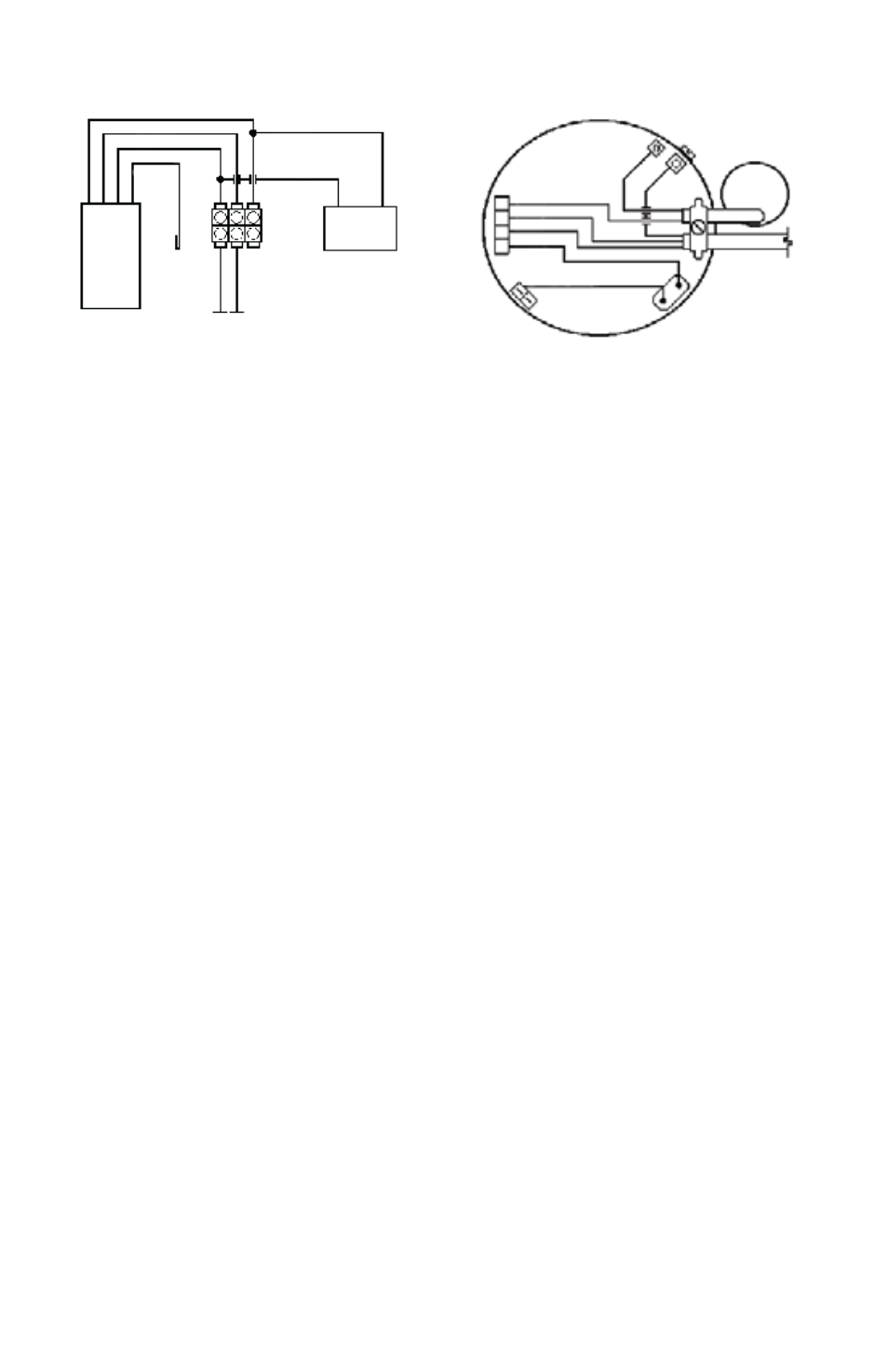
Wiring Diagrams
Operation
1. Completely fill the system before operating the circulator. Do not start the circulator until the
system has been filled. Make sure the isolation valves are fully open and that there is water in the
circulator.
2. Purge air from the system prior to operating the circulator. These two steps are very important. The
circulator should never be allowed to run dry. This can severely damage the circulator and will void the
warranty.
3. Operate the circulator for approximately 10 minutes to purge any remaining air in the system. It
may be necessary to open a discharge valve, port and/or fixture to ensure that the air has been purged.
The circulator should be running quietly. If a “gurgling” noise is present it may mean there is still air in
the system. Turning the circulator on and off several times will generally clear the remaining air. If this
“gurgling” noise persists, recheck the system and re-purge the air. System and circulator should now
operate quietly and efficiently.
4. Dry Run Internal Thermostat: All plastic housing model pumps are provided as standard with an
integral dry run protection thermostat that turns pump off when pump runs dry (thermostat off at
212ºF + 10ºF). If left unattended, the thermostat will automatically reset within a relatively short
amount of time when the unit cools down, thereby allowing the pump to again begin operation (at
176ºF+ 13ºF). Depending on the system conditions, many times one or two of these off/on cycles will
correct an air bound dry run condition by itself with no harm done to the pump, thereby allowing
continued trouble free operation. However, if the off/on cycling persists then measures should be taken
to correct the problems in the circulation system causing the on/off cycling. Stainless housing pumps
are not provided with a dry run thermostat.
Maintenance
1. Since the rotor/impeller unit (see exploded views) is the only moving part, its replacement and/or the
replacement of the motor is simple to accomplish.
2. After the power has been disconnected remove the screws holding the pump housing to the motor
(in the case of model SM-909 and SM-1212 units) or using a counter clockwise motion remove the
screw ring housing to motor connection on model SM-303 units.
3. Remove the “O” ring from the pump housing.
4. Remove and replace the rotor. Check to make sure that the ceramic bearing on the motor is intact
and is not chipped or otherwise damaged.
5. Replace the “O” ring with a new one and reverse the disassembly procedure to reassemble the
pump.
6. Since these units are self lubricated by the pumped fluid, they never need external lubrication.
7. Pump should be drained when subjected to freezing temperatures.
8. If provided, the suction line strainer should be cleaned at regular intervals.
Warranty
Laing recirculation pumps are warranted against defects in materials and workmanship for 24 months from
the date of manufacture (see mfg. date label on pump) or twelve (12) months from date of user purchase,
with proof of purchase, whichever is later. In order to receive warranty considerations, the product must be
returned prepaid to the company from which it was originally purchased. If the pump is found defective,
the pump will be replaced or in the case of wholesale customers, appropriate purchase credit will be issued.
Prior to returning any defective pump to Laing for warranty consideration, contact the Laing factory for
an RMA tracking number. Any claim for consequential damages resulting from a pump malfunction is not
covered by the Laing warranty. Additional warranty details are available on request.
Fig. 4 - SM-909 and SM-1212 models
Brown
Black
White
Black
or White
C
B
A
I
Black or Red
TCO
Blue
Green
Ground Lug
Capacitor
TCO Settings
Open 212ºF + 10ºF
Close 176ºF +- 10ºF
Fig. 3 - SM-303 models
Black
Brown
Yellow
Red
Pump
Taped End
Black White
115v or 230v line In
Orange
Orange
Capacitor