Manual – Xylem Expert 3400 User Manual
Page 6
6
Manual
Manual Expert 1400/3400 GB 0704
MJK Automation A/S
Byageren 7
DK-2850 Naerum
Denmark
Tel.: +45 45 56 06 56
Fax: +45 45 56 06 46
[email protected]
www.mjk.com
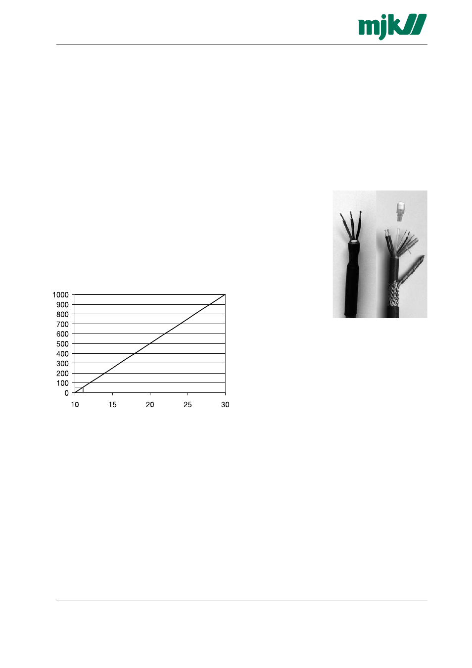
Designation of wires, cutting & stripping the cable
The factory delivered cable has the wires marked with
the numbers 1 - 2 - 3 as to the table to the right. If the
cable needs to be cutted and stripped, the shield should
be connected as the no. 3 wire.
Do NOT connect any of the colored programming wires
as it may damage the transmitter. The programming
wires should be cut off in different lengths to prevent
them from short circuit.
Take care not to block or squeeze the air pressure
compensation tube ➄.
Designations:
1: Positive (+) wire, red
2: Negative (-) wire, brown
3: Shield
(NOT signal ground!)
4: Moisture filter for com-
pensation tube
5: Air pressure
compensation tube
6: Programming wires
Factory delivery
➁
➀
➃
➂
Cutted and
stripped
➁
➃
➂
➄
➅
Do not connect a programming unit to the transmitter
or make any attemt to program the tranmitter while the
transmitter is located in an explosion hazardous zone!
Electrical mounting
Cable length vs. supply voltage
The cable can be lengthened with any type of cable
using connection box 202922. Although the measuring
signal is not sensitive to electrical noise, we recommend
the use of a screened cable.
Ensure that no moisture can enter the pressure compen-
sation tube inside the cable.
The length of the cable is only limited by the total resist-
ance (A) of the cable conductors + the input impedance
of the analog input on the MJK 704, MJK 713, PLC etc.
(typically 10 to 100
Ω) and the available supply voltage
(B) (typically 24 V DC).
Example:
The nominal resistance for 1 conductor in a transmitter
cable is 0,036
Ω/m. A standard 12 m cable will therefore
add 2 x 0,036 x 12 = 0,86
Ω to the loop resistance. If the
analog input has an impedance of 50
Ω., the total
resistance will be approx. 51
Ω.
(B) Supply voltage [V DC]
Necessary supply voltage in relation to the total loop resistance.
(A) Total loop resistance [
Ω]
According to the diagram above, approx. 12 V DC will
be sufficient.
➀