0 electrical connections – Xylem CL500 ONLINE CHLORINE ANALYZERS MODBUS User Manual
Page 4
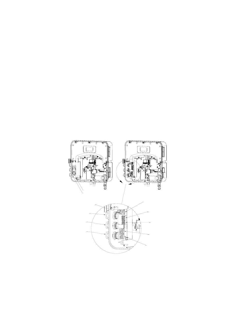
2.0 Electrical Connections
All of the electrical connections to the instrument are made at the termination area, which
is located on the portion of the instrument. The connections are labeled and are self-
descriptive (see Figure 1). Please follow all local and government recommendations and
methods for installation of electrical connections to and between the instrument and other
peripheral devices.
Plugs are inserted into cable bulkheads when shipped, to ensure a watertight seal. These
plugs should be removed and discarded as required when cabling to this connection.
The bulkhead will accept cable diameters from 5.8mm (.230 in.) up to 10 mm (.395 in.).
The terminals are designed to accept wires in the range of 14-28 AWG. All wires should
be stripped to a length of 6 mm
It is the user’s responsibility to assure that the watertight seal is maintained after the
terminal box has been wired for operation. If any of the bulkheads are not tightened
properly around a cable or plug, the ratings of the instrument will be jeopardized and there
is a possibility of creating a shock hazard.
Note: Only qualified electricians should be allowed to perform the installation of the
instrument as it involves a line voltage that could endanger life.
High Voltage Cover
Captive Screw
Power
Terminal
Block
Alarm #2
Terminal
Block
Alarm #1
Terminal
Block
RS-485
Terminal
Block
4-20mA
Terminal
Block
Power Cable
Strain Relief
Anchor
Power
Bulkhead
Alarms
Bulkhead
Communication
Bulkhead
Figure 1: Electrical Connections for the Instrument
CL500 Modbus (3/09)
Rev. 1.3
2