Xylem C3V CHEMICAL METERING PUMPS User Manual
Page 3
Page 2
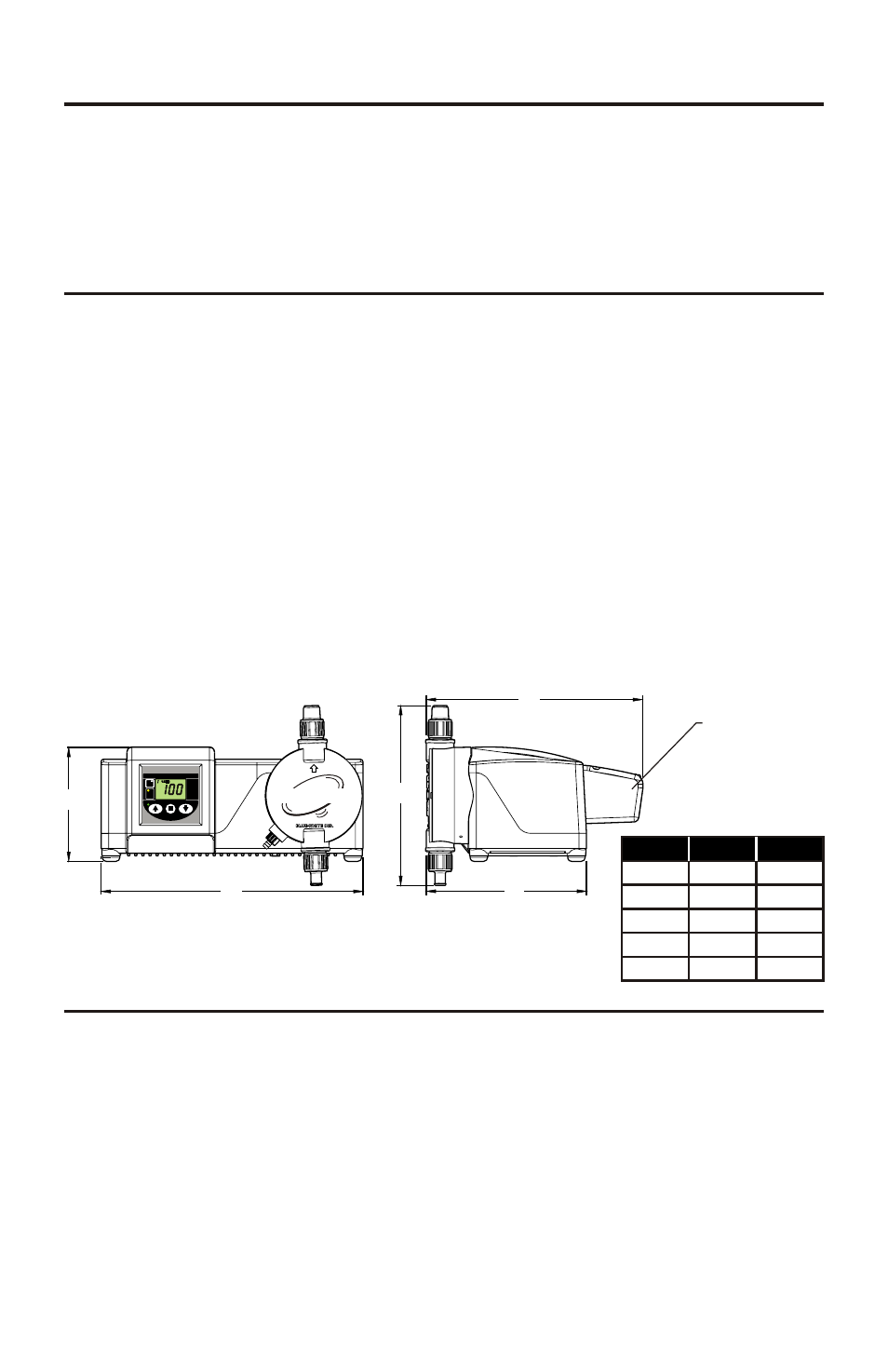
2.0 Specifications
Maximum Working Pressure* ..............175 psig / 12.1 bar
o o
Maximum Fluid Temperature . ..............130 F / 54 C
o o
Ambient Temperature Range . ..............14 to 115 F / -10 to 46.1 C
Output adjustment Range ...... ..............1-100% in 1% increments
Turn Down Ratio.................................... 100:1
Duty Cycle .. .............. .............. ..............Continuous
Maximum Viscosity .. .............. ..............1,000 Centipoise
Maximum Suction Lift............. ..............15 ft. water / 4.5 m water
Enclosure Rating ...... .............. ..............NEMA 4X / IP66
Power Requirements .............. ..............115v, 50/60Hz 1.5 Amp
230v, 50/60Hz 0.7Amp
Shipping Weight ....... .............. ..............29 lb. (approx.)
Dimensions:
Page 3
1.0 Introduction
Congratulations on purchasing the C3 Diaphragm Metering Pump. The
C3 is designed to inject chemicals into piping systems and is capable of
injecting against a high system pressure up to 175 PSI / 12.1 bar*.
C3
C3
* Depending on model selection.
CHEM-PRO
TM
tm
CHEM-PRO
C3V | Diaphragm Metering Pump
Made in the USA
MODE
PRIME
Program
Minimum
Maximum
Blue-White Ind.
IP66
NEMA 4X
Junction
Box
A
B
C
D
E
3.0 Features
Oversized PVDF double ball valves.
Operator friendly digital touch pad.
– Easy to read Back Lit LCD display
– Display percentage of motor speed
DFD, Built-in Diaphragm Failure Detection system.
Priming / degassing valve built into the pumphead
NEMA 4X and IP66 rated enclosure
Dim
Inches
mm
A
B
C
D
E
5-3/4”
13-1/8”
9”
8”
10-3/4”
144.8
332.7
228
203.2
274.3
Series
DFD
(Leak Detection)
FVS**
(Flow Verification)
Junction
Box
Pulsed* Batch
Alarm Relay
3 Amp
C3F
C3V
External Communications (input)
Output
Series Comparison:
P
P
P
P
P
P
P
P
P
P
P
P
P
P
P
P
P
P
Optional
0-10 VDC
P
P
* Also known as Frequency Mode
** Requires Micro-Flo Sensor sold separately
4-20 mA
P
P
TABLE OF CONTENTS
1.....Introduction ......................................................................................3
2.....Specifications ............. .............. .............. .............. .............. ..............3
3.....Features ....... .............. .............. .............. .............. .............. ..............3
4.....Unpacking .... .............. .............. .............. .............. .............. ..............4
5.....Installation .... .............. .............. .............. .............. .............. ..............4
5.1..Mounting location .............. .............. .............. .............. ..............4
5.2..How to install the tubing and fittings. .............. .............. ..............6
5.3..Diaphragm Failure Detection.......................................................7
5.4..Flow Verification System............................................................. 8
6.....C3F External Input/Output Signal Connection....... .............. ..............9
6.1..How to operate the C3F ............................................................10
7.....C3V External Input/Output Signal connection....... ............... .............11
7.1..How to operate the C3V .... .............. .............. .............. ..............12
7.2..Operating Mode 1 - Output adjusted manually.............. ..............13
7.3..Operating Mode 2 - 4 - 20 mA input mode.................... ..............13
7.4..Operating Mode 3 - 0 - 10 VDC Mode.................. ........ ..............16
7.5..Operating Mode 4 - Frequency Mode (Hz)..... .............. ..............18
7.6..Operating Mode 5 - Batch Mode ...... .............. .............. ..............21
8.0..Measuring the Pump’s Output - volumetric Test................................. 23
9.0..How to maintain the pump.................................................................. 24
9.1..Routine Inspection and Maintenance.......................................... 24
9.2..How to clean the pump................................................................24
Pump head and Valve exploded view drawing ...... .............. ..............25
Replacement parts drawing ...... .............. .............. .............. ..............26
Replacement parts list .............. .............. .............. .............. ..............27
Warranty information .. .............. .............. .............. .............. ..............30
Authorized service centers ....... .............. .............. .............. ..............31