H-424ms – Xylem H-424MS V1.1 User Manual
Page 9
1.7 Making SDI-12 Connections
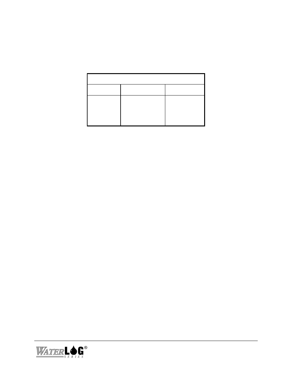
The H-424MS enclosure has a 4-pin SDI-12 connector. The power for the H-424MS and the
radio is supplied by the SDI-12 +12V input. Table 1 shows the proper connections. Refer to the
wiring diagram printed on the H-424MS's product label for the connector pinout.
SDI-12 Connector
Pin
Name
Wire Color
1
2
3
4
+12Volt DC
SDI-12 Data
Ground
Ground
Red
White
Black
Shield
Words of caution:
!
Even though the H-424MS operates in a low power mode, the transmitter requires 800mA
for short bursts. Make certain your wiring and battery is capable of supplying sufficient
current .
!
Keep the lead wires as short as possible.
!
Use shielded cables in noisy environments.
!
Connect the ground post to a good earth ground.
1.8 Troubleshooting
The H-424MS circuit board has a red LED indicator which is lighted when the radio is powered.
After installing the H-424MS's, antennas and wiring; make the following tests:
1.8.1 Testing With Power Save Jumpers = OFF:
The LED indicators in both master and slave should be continually illuminated. Using the
transparent mode of your data logger issue a “0I!" command. The master H-424MS should
respond with a SDI-12 identification string. Issue a command to your remote SDI-12 sensor.
Check for the correct response.
1.8.2 Testing With Power Save Jumpers = ON:
The LED indicator in the slave should blink every 15 seconds. If you have changed the Wake
Interval setting, the LED should blink at your chosen interval. The LED indicator in the master
should be OFF. Using the transparent mode of your data logger, issue a “0I!" command. The
master H-424MS should respond with a SDI-12 identification string. Issue a “0M!” command,
the H-424MS should respond with “00161
The next time the slave powers up its radio, the slave should detect inbound messages and
H-424MS
Operation 1-5