H-424ms – Xylem H-424MS V1.1 User Manual
Page 6
Normally the H-424MS operates as a transparent SDI-12 to SDI-12 bridge. However, in order to
wake the remote end of the link from sleep the master H-424MS can be addressed itself as a
“sensor”. The H-424MS comes from the factory with its address set to “0". When the master H-
424MS detects address 0 it responds as a SDI-12 sensor and does not pass the command to the
remote site(s). Issuing the “0M!” command causes the H-424MS to perform a wakeup sequence
to the remote sites. The timing is controlled by two timers; a Wakeup and an Inactivity timer.
The settings of these programable timers is stored in EEPROM within the H-424MS;
Power Save Operating Sequence
1.
The data recorder first issues a “0M!” command to the master H-424MS module.
2.
The master H-424MS responds to the command as a pseudo “sensor”, and reports the
measurement will take a fixed period of time to complete. The reported time is
determined by the Wakeup Interval time setting + 1 seconds.
3.
The master H-424MS transmits wakeup nulls every 40usec during the “measurement”.
4.
Remote H-424MS modules periodically wake up and check for inbound messages. The
wake up is initiated by a low power circuit controlled by the Wakeup Interval setting.
5.
If an inbound message is detected while awake, the remote module remains awake for a
period set by the Inactivity Timer.
6.
At the completion of the “0M!” command, both the master and slave H-424MS modules
are awake and can service a SDI-12 command. At this point the data logger issues
measurement or other commands to the actual remote sensors.
7.
If no additional commands are sent by the data logger, both master and remote modules
resume their low power sleep mode after their respective Inactivity Timers run down.
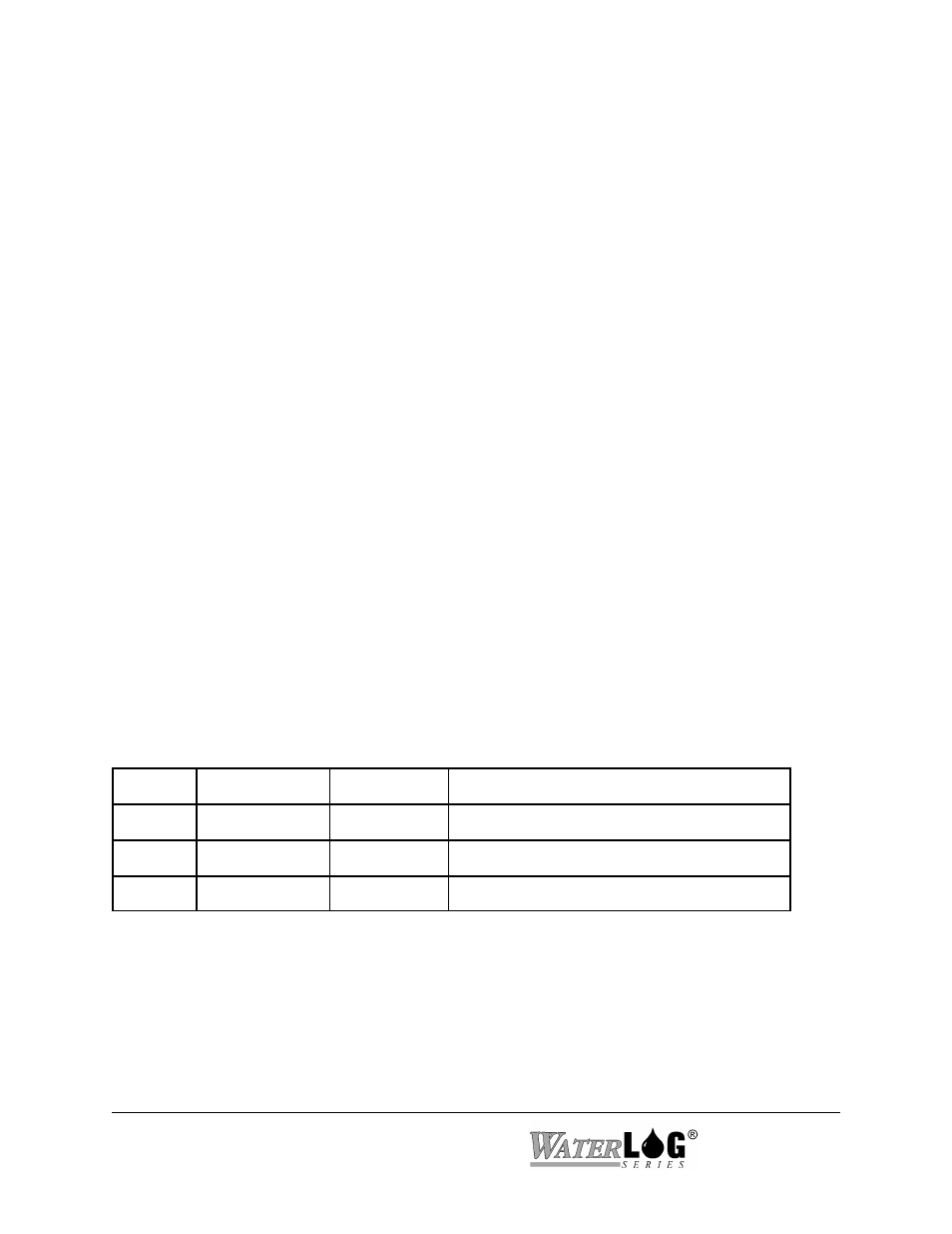
1.3 Setting the Jumpers
The H-424MS circuit board has three push-on jumpers which must be properly set. Each jumper
is a 3-pin stake-pin header with two possible positions. The jumpers can be accessed by opening
the front cover of the enclosure.
Jumper
Function
Options
Description
J2
Mode
Master/Slave
Selects either Master or Slave operation
J3
Power Save
On/Off
Enables or disables the power save feature
J6
Loopback Test
On/Off
Enables or disables the loopback test mode
All H-424MS's in the installation MUST have the same power-save jumper selection. Leave the
Loopback Test jumper in the OFF position for normal operation.
1-2 Operation
H-424MS