Installation, Start-up – Xylem CO COM IM User Manual
Page 16
en
16
5. Installation
The product must be handled with care; impacts can cause damage without any visible external signs.
See figs. 1 and 2 for correct installation.
6. Start-up
6.1 Electrical connection
Make sure that the rated voltage corresponds to the supply voltage.
Ground the pump before making any other connection.
We recommend that a high sensitivity differential switch (30 mA) be in-
stalled as extra protection against lethal electric shocks in the event of
faulty grounding.
Connect the pump to the mains using a multiple-pole switch or other device ensuring multiple-pole discon-
nection (interruption of all the supply wires) from the mains, with a contact separation of at least 3 mm.
Remove the terminal board cover by first removing the screws.
Carry out the connections as indicated on the back of the terminal board cover, and as shown in fig. 3 for
single-phase versions and in fig. 4 for three-phase versions.
DANGER
RISK OF
ELECTRIC SHOCK
RECOMMENDED POWER CABLE SECTION
CABLE TYPE
H05VV-F
H05RN-F
H07RN-F
Single-
3x0.75 mm
3x0.75 mm
3x1 mm
phase
3x1 mm
3x1 mm
3x1.5 mm
Three-
4x0.75 mm
phase
4x1 mm
4x1.5 mm
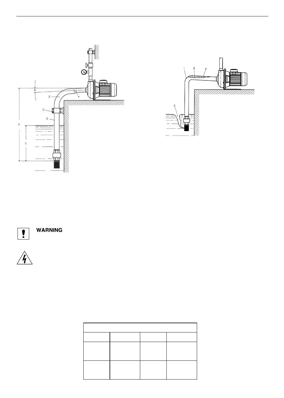
FIGURE 2
Incorrect installation
1 = Sharp bend: high flow re-
sistance.
2 = Insufficient immersion:
sucking air.
3 = Negative gradient: air
pockets.
4 = Pipe diameter < pump
port diameter: high flow
resistance.
FIGURE 1
Correct installation
A = Eccentric reductions.
B = Positive gradient.
C = Good immersion.
D = Large bends.
E = Suction pipe diameter ≥ pump port-
diameter.
F = Suction lift depends on the pump and
installation (*).
G = The pipes should not weigh on the
pump but on separated supports.
(*) The suction lift is determined based on
liquid temperature, flow resistance and
NPSH required by the pump.