Xylem IMVS R01 Model VS Vertical Industrial Turbine Pumps User Manual
Page 11
11
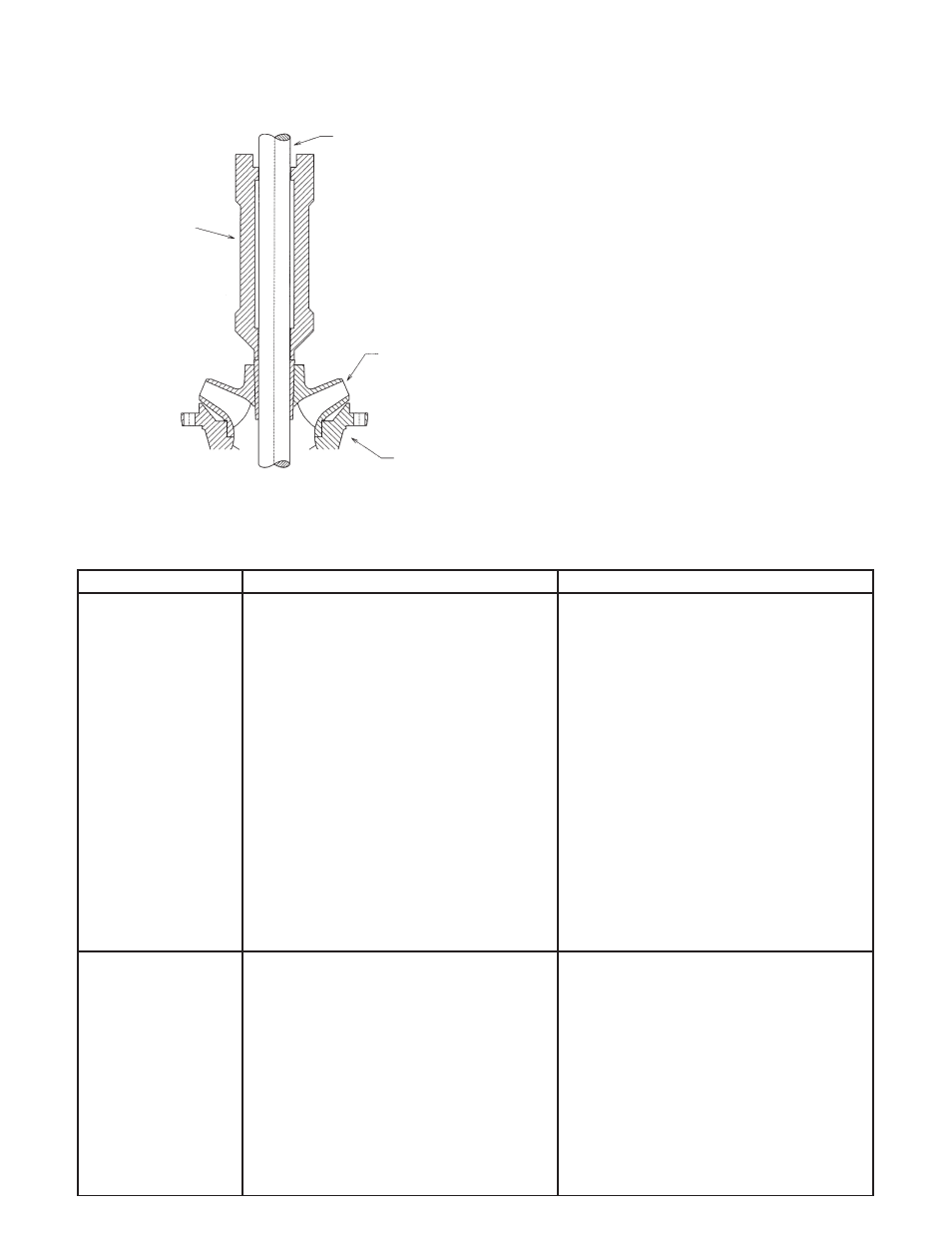
D. Hold impeller firmly against the motor adapter
and drive the taperlock into place with the ta-
perlock driver. See Figure 5. After the impeller is
secured in position, the top end of the taperlock
should be
1
/
8
" above the impeller hub.
Figure 5 – Install the Impeller
E. Put a little grease on the shaft where the inter-
mediate bearing will be. Slip intermediate bowl
over the shaft and bolt or screw it onto the motor
adapter.
F. Place the next impeller over the shaft and continue
to assemble as explained above.
G. After assembling the last impeller, slide the up-
thrust washer over the shaft before assembling the
top intermediate.
H. Slide the discharge case and top intermediate
bowl over the shaft and bolt it to the second in-
termediate bowl. If the pump has a built-in check
valve, install the check valve before installing the
discharge adapter.
I. When the bowl is completely assembled, unlock
the shaft and remove the assembly jig. Rotate the
shaft by hand to see whether it rotates freely. Push
the shaft all the way in and then pull it all the
way out to check the lateral clearance. The lateral
should be between 0.187" to 0.250".
J. Install the square key in the keyway at the motor
end of the pump shaft. Slide the shaft coupling
over the shaft and secure it to the key with two
setscrews.
SECTION 8 — TROUBLESHOOTING CHART
In case of difficulties, refer to the chart to locate basic problems with the system. Once the problem is located, refer to
specific sections in this manual for details.
CONDITION
PROBABLE CAUSE
REMEDY
PUMP WILL
1. Motor overload protector trip
1. Allow motor to cool, overload will
NOT RUN
a. Incorrect control box.
automatically reset. Investigate cause
b. Incorrect connections.
of overload.
c. Faulty overload protector.
a-e. Have a qualified electrician inspect
d. Low voltage.
and repair, as required.
e. Ambient temperature of control box
or starter too low.
f. Pull the pump, examine and clean.
f. Pump bound by foreign matter.
Adjust set depth as required.
2. Blown fuse, broken or loose electric
2. Check fuses, relays or heater elements
connections.
for correct size capacitor and all electrical
connections.
3. Motor control box or starter not in
3. Make sure box is in upright position.
proper position.
4. Cable insulation damaged.
4. Locate and repair as per instructions.
5. Splice may be open or grounded.
5. Check resistance between cable leads
with ohmmeter. If open or grounded,
pull pump and resplice.
6. Faulty pressure switch.
6. Repair or replace.
7. Faulty liquid level control.
7. Check relay, wires and electrodes.
PUMP RUNS
1. Line check valve backward.
1. Reverse check valve.
BUT NO WATER
2. Pump is air-bound.
2. Successively start and stop pump until
water flows normally.
3. Lift too high for the pump.
3. Review performance requirement.
4. Suction screen or impeller plugged,
4. Pull the pump and clean, check well
or pump in mud or sand.
depth. Raise setting if necessary.
5. Pump not submerged.
5. Check water level. Lower pump if
permissible.
6. Well may contain excessive amounts
6. Start and stop pump several times. If this
of air or gas.
does not remedy conditions, pump may
not be able to cooperate because of too
much gas in the well.
7. Three-phase unit running backwards.
7. Reverse rotation.
SHAFT
IMPELLER
BOWL
TAPERLOCK
DRIVER
ASSEMBLY
POSITION