3 install the pump, 1 install the pump on a concrete foundation, 2 electrical installation – Xylem IM254R01 e-HM Series User Manual
Page 6: Connect the cable, 5 commissioning, startup, operation, and shutdown, 1 prime the pump, 2 check the rotation direction (three-phase motor)
4.3 Install the pump
4.3.1 Install the pump on a concrete foundation
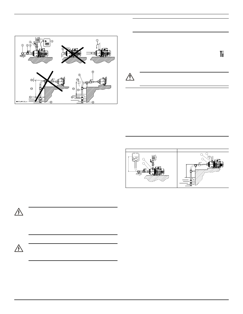
1.
Piping support
2.
On-off valve
3.
Flexible pipe or joint
4.
Check valve
5.
Control panel
6.
Do not install elbows close to the pump
7.
Bypass circuit
8.
Eccentric reducer
9.
Use wide bends
10. Positive gradient
11. Piping with equal or greater diameter than the suction port
12. Use foot valve
13. Do not exceed maximum height difference
14. Ensure adequate submersion depth
1.
Anchor the pump onto the concrete or equivalent metal structure.
• If the liquid temperature exceeds 50°C, the unit must be
anchored only by the motor bracket side and not also by the
side of the inlet supporting bracket
• If the transmission of vibrations can be disturbing, then pro-
vide vibration-damping supports between the pump and the
foundation.
2.
Remove the plugs covering the ports.
3.
Assemble the pipe to the pump threaded connections.
Do not force the piping into place.
4.3.2 Electrical installation
Precautions
Electrical Hazard:
• Make sure that all connections are performed by quali-
fied installation technicians and in compliance with the
regulations in force.
• Before starting work on the unit, make sure that the unit
and the control panel are isolated from the power sup-
ply and cannot be energized.
Grounding (earthing)
Electrical Hazard:
• Always connect the external protection conductor to
ground (earth) terminal before making other electrical
connections.
Connect the cable
1.
Connect and fasten the power cables according to the wiring dia-
gram under the terminal box cover.
a)
Connect the ground (earth) lead.
Make sure that the ground (earth) lead is longer than the
phase leads.
b)
Connect the phase leads.
NOTICE:
Tighten the cable glands carefully to ensure the protection against
the cable slipping and humidity entering the terminal box.
2.
If the motor is not equipped with automatic reset thermal protec-
tion, then adjust the overload protection according to the nominal
current value of electric pump (data plate).
5 Commissioning, Startup,
Operation, and Shutdown
Precautions
WARNING:
Make sure that the drained liquid does not cause damage or
injuries.
NOTICE:
• Never operate the pump below the minimum rated flow.
• Never operate the pump with the delivery ON-OFF valve closed
for longer than a few seconds.
• Do not expose an idle pump to freezing conditions. Drain all liq-
uid that is inside the pump. Failure to do so can cause liquid to
freeze and damage the pump.
• The sum of the pressure on the suction side (water mains, gravity
tank) and the maximum pressure that is delivered by the pump
must not exceed the maximum working pressure that is allowed
(nominal pressure PN) for the pump.
• Do not use the pump if cavitation occurs. Cavitation can damage
the internal components.
5.1 Prime the pump
H>0
H<0
+H
-H
1
2
1
2
3
HM122_M014_A_sc
1.
Fill plug
2.
Drain plug
3.
Funnel
Installations with liquid level above the pump (suction head)
Close the on-off valve located downstream from the pump.
Installations with liquid level below the pump (suction lift)
Open the on-off valve that is located upstream from the pump and
close the on-off valve downstream.
5.2 Check the rotation direction (three-phase
motor)
Follow this procedure before start-up.
1.
Start the motor.
2.
Stop the motor.
3.
If the rotation direction is incorrect, then do as follows:
a)
Disconnect the power supply.
b)
In the terminal board of the motor or in the electric control
panel, exchange the position of two of the three wires of the
supply cable.
c)
Check the direction of rotation again.
5 Commissioning, Startup, Operation, and Shutdown
Model e-HM Installation, Operation, and Maintenance Manual
5