Controller dimensions 9: troubleshooting, Continued) – Xylem IM156 R06 1AB2 & 2AB2, Aquavar ABII Variable Speed Pump Controller User Manual
Page 11
11
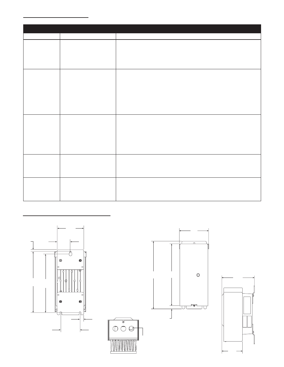
10: CONTROLLER DIMENSIONS
9: TROUBLESHOOTING
(continued)
10: CONTROLLER DIMENSIONS
9: TROUBLESHOOTING
RED LIGHT CODES
Indicator Code Status
Description
5 Blinks
Short Circuit
Check wiring for shorting phase to phase and phase to ground. Turn
power to controller off and wait 5 minutes. Remove controller
access panel. Disconnect motor leads marked T1, T2, and T3. Measure
resistance between all motor leads using an ohmmeter. NOTE: Motor
winding resistance is typically 2 to 10 OHMS depending on motor.
6 Blinks
Ground Fault
Check wiring for shorting phase to ground. Turn power to controller
off and wait 5 minutes. Remove controller access panel. Disconnect
motor leads T1, T2, T3, and Ground from controller. Measure
resistance between all motor leads and ground using a Megohmmeter.
Connect one Megohmmeter lead to any one of the motor leads and
the other to ground lead. Set Megohmmeter to 500V DC output.
Resistance readings less than 500,000 ohms or 0.5 Megohms indicate
a damaged motor.
7 Blinks
High Temperature
This fault is caused by a high temperature inside of the controller. The
controller will shut off when the temperature inside the controller
reaches 158º F (70º C). The controller will turn back on when the
temperature inside the controller reaches 150º F (65.5º C). Avoid
installing the controller where ambient temperatures exceed 104º F
(40º C). Avoid installing the controller where it is exposed to direct
sunlight.
8 Blinks
Over Voltage
Measure input voltage using an AC voltmeter. Connect the positive
and negative leads to L1 and L2 on the Aquavar ABII controller. Verify
line input voltage is not greater than 264 VAC for 1AB2 and 2AB2
controllers and 132VAC for 1151AB2.
9 Blinks
Motor Overload
This fault is indicated when the current supplied to the motor exceeds
the Motor Overload Setting on the Aquavar ABII controller. Refer to
Section 7, Setting the Motor Overload DIP Switches for details. If
switches are set according to Section 7, check motor.
(135.36)
5.33
(259.08)
10.20
(237.06)
9.33
(12.07)
.48
(157.90)
6.22
(99.06)
3.90
(114.30)
4.50
(57.15)
2.25
(8.38)
.33
(242.04)
9.53
(232.56)
9.16
(81.28)
3.20
(16.51)
.65
1
∨
2
”
Liquid
Tight
(135.36)
5.33
(259.08)
10.20
(237.06)
9.33
(12.07)
.48
(157.90)
6.22
(99.06)
3.90
(114.30)
4.50
(57.15)
2.25
(8.38)
.33
(242.04)
9.53
(232.56)
9.16
(81.28)
3.20
(16.51)
.65
1
∨
2
”
Liquid
Tight
(135.36)
5.33
(259.08)
10.20
(237.06)
9.33
(12.07)
.48
(157.90)
6.22
(99.06)
3.90
(114.30)
4.50
(57.15)
2.25
(8.38)
.33
(242.04)
9.53
(232.56)
9.16
(81.28)
3.20
(16.51)
.65
1
∨
2
”
Liquid
Tight
(135.36)
5.33
(259.08)
10.20
(237.06)
9.33
(12.07)
.48
(157.90)
6.22
(99.06)
3.90
(114.30)
4.50
(57.15)
2.25
(8.38)
.33
(242.04)
9.53
(232.56)
9.16
(81.28)
3.20
(16.51)
.65
1
∨
2
”
Liquid
Tight