Floa t switch adjustment – Bell & Gossett DN0129D Series CMU User Manual
Page 3
3
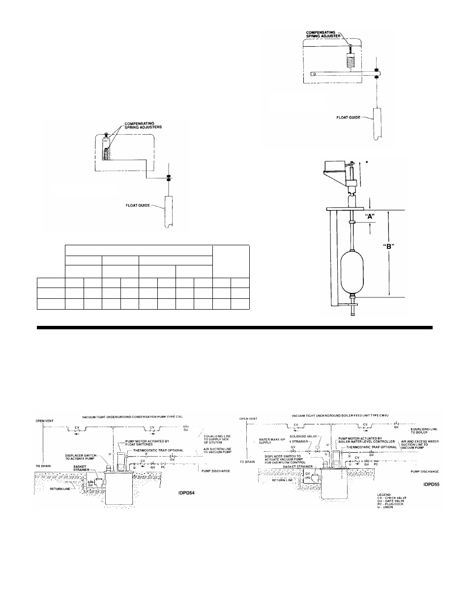
FLOA
T SWITCH ADJUSTMENT
The float positions ar
e factory set. These positions should be
reset as necessary. Minor deviation is permissible to meet local
requirements. The settings must avoid “short cycling” of the
pumps.
The float switch and mechanical alternator each have an inter-
nal compensating spring to balance the weight of the float
guide rod. These springs are to have just enough tension or
compression on the float switch to counterbalance the guide
rod (but not the float).
PIPING DIAGRAMS V
ACUUM TIGHT
UNDERGROUND CONDENSATE &
BOILER FEED UNITS
T
ype CVU units are designed for use as a mechanical lift in a
vacuum heating system. They are also used to return conden-
sate under vacuum to a boiler feed tank. They have vacuum
tight displacer switch(es) for pump control.
Type CMVU units have water make-up valve and are actuated
by boiler controller. They are designed for use in a vacuum sys-
tem to discharge condensate directly to the boiler.
It is necessary to pipe the vent line to atmosphere using full
vent port size piping with check valves installed as shown on
diagrams. It is also recommended that the vent line be
“dripped” to drain to prevent an accumulation of condensate in
the vent pipe.
*
MAKE SETTINGS
WITH ARM AT
HIGHEST POSITION
MECHANICAL
ALTERNATOR
FLOAT SWITCH
2DFS01
PIPING DIAGRAM FOR UNDERGROUND
CONDENSATE UNIT USED
IN A VACUUM SYSTEM
PIPING DIAGRAM FOR UNDERGROUND
BOILER FEED UNIT USED
IN A VACUUM SYSTEM
FLOAT SETTING CHART
Condensate Unit
Single
Duplex
Duplex 2 Float Switch
Boiler
Primary
Stand-By
Feed
Unit
(Mech. Alt.)
Float Switch
Float Switch
Unit
Depth
“A”
“B”
“A”
“B”
“A”
“B”
“A”
“B”
“A”
“B”
36"
11"
22"
8
1
/
2
"
21" 12
1
/
2
" 22"
11"
22"
14"
22"
48"
11"
34"
8
1
/
2
"
33" 12
1
/
2
" 34"
11"
34"
26"
34"