Changing rotation – Xylem 8200 Series Base Mounted Centrifugal Fire Pumps AC2675 REV.C User Manual
Page 25
CHANGING ROTATION
WARNING: Rotating Components
Hazard
25
Do not operate pump without all guards in place. Failure
to follow these instructions could result in serious
personal injury or death and property damage.
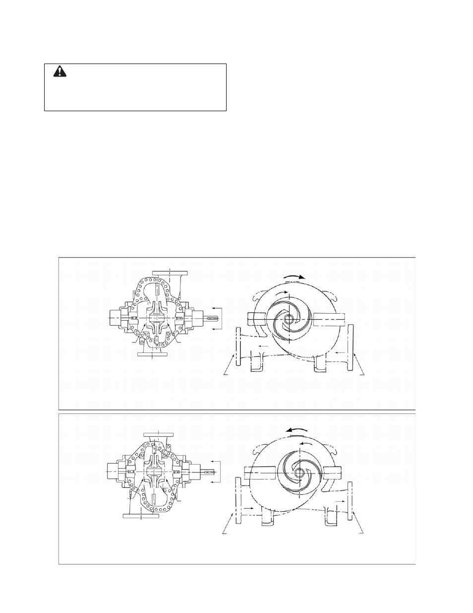
8200 Series centrifugal pumps can be operated
clockwise or counterclockwise when viewed from
the coupling end of the pump. If you wish to
reverse the suction and discharge nozzles; i.e.,
change rotation, this can be accomplished with the
same pump as follows:
1. Remove the impeller from the shaft, and
relocate the two impellers per Figure 10 for the
desired rotation. (Follow the disassembly
procedures given in this manual.)
2. With the rotating element out of the
casing, remove the casing from the base
and turn 180°. (Factory bases are drilled
for both rotations.)
3. Set the rotating element back in the
casing and reassemble the pump.
NOTE: The impeller and casing are in the
same relationship to each other as they were
originally. The shaft and motor are also in the
same relationship to each other as they were
originally. The suction and discharge are
offset, so the piping will need to be changed
to accommodate the new flange locations.
4. Reassemble the pump and realign the
coupling as called for in the alignment
instructions.
5. The rotation of the motor must be
changed by switching the motor leads.
NOTE: Unless the motor rotation is reversed
the impeller will run backward.
SUCTION
CW ROTATION
“A”
“A”
2ND STAGE
IMPELLER
1ST STAGE
IMPELLER
IMPELLER VANE
ORIENTATION “A-A”
DISCHARGE
DISCHARGE
SUCTION
CLOCKWISE ROTATION
VIEWED FROM THE COUPLING END
CCW ROTATION
DISCHARGE
“A”
“A”
1ST STAGE
IMPELLER
2ND STAGE
IMPELLER
IMPELLER VANE
ORIENTATION “A-A”
SUCTION
DISCHARGE
SUCTION
COUNTERCLOCKWISE ROTATION
VIEWED FROM THE COUPLING END
FIGURE 10 – CORRECT RELATIONSHIP OF THE IMPELLERS AND CASING