Xylem 8200 Series Base Mounted Centrifugal Fire Pumps AC2675 REV.C User Manual
Page 12
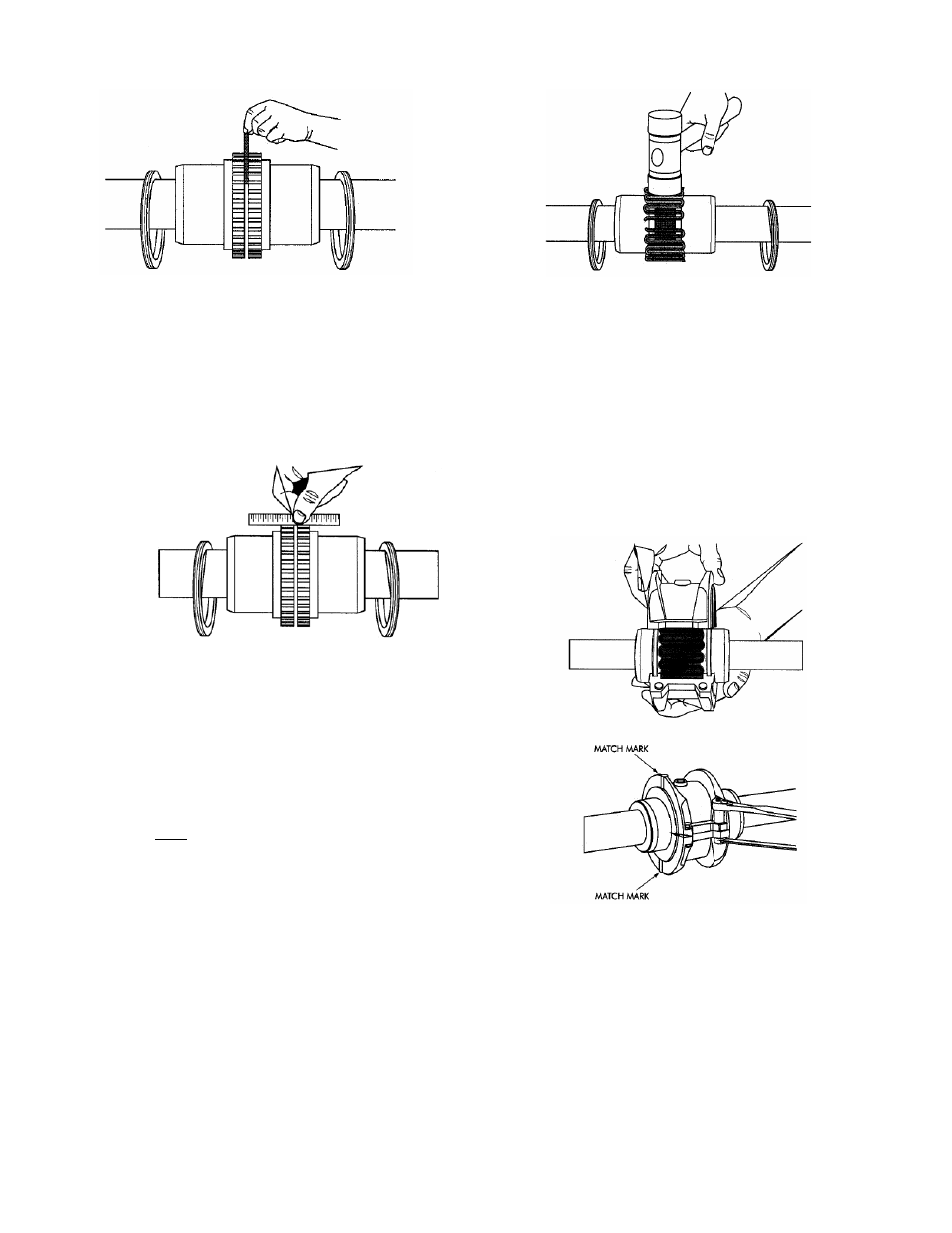
FIGURE 7C – USING SPACER BAR
9. Align so that a straight edge rests within
the limits shown in Figure 7D on both
hubs as shown below and also at 90°
intervals without rotating the coupling.
Check with feelers. The clearance must
not exceed the PARALLEL OFFSET
installation limits specified in Figure 7H.
FIGURE 7D – USING STRAIGHT EDGE
10. If adjustment is needed, loosen the motor
bolts and add (or remove) an equal
amount of shims under each motor foot to
align the height. To correct side
misalignment, strike the side of the motor
foot with a mallet.
11. Tighten the motor bolts and check again.
If a correction is made, re-check alignment
in all directions. Repeat this process until
the desired result is obtained.
12. Pack gap and grooves with coupling
vendor supplied grease before inserting
grid. When grids are furnished in two or
more segments, install them so that all cut
ends extend in the same direction as
shown below. This will ensure correct grid
contact with non-rotating pin in cover
halves.
13. Spread the grid slightly to pass over the
coupling teeth and seat with a soft mallet.
FIGURE 7E – SEATING THE GRID
14. Pack the spaces between and around the
grid with as much as coupling vendor
supplied grease as possible and wipe off
the excess until flush with the top of the
grid.
15. Position seals on hubs to line-up with
grooves in cover. Position gaskets on
flange of lower cover half and assemble
covers so that the match marks are on the
same side.
FIGURE 7F – COVER INSTALLATION
16. If the shafts are not horizontal, or coupling
is to be used vertically, assemble cover
halves with the lug and match mark UP or
on the high side. Push gaskets in until
they stop against the seals and secure
cover halves with fasteners, tightening to
torque specified in Figure 7H. Ensure
gaskets stay in position during fastener
tightening.
12