AVSL Citronic CX34 User Manual
Page 3
3
170.929UK, 170.932UK User Manual
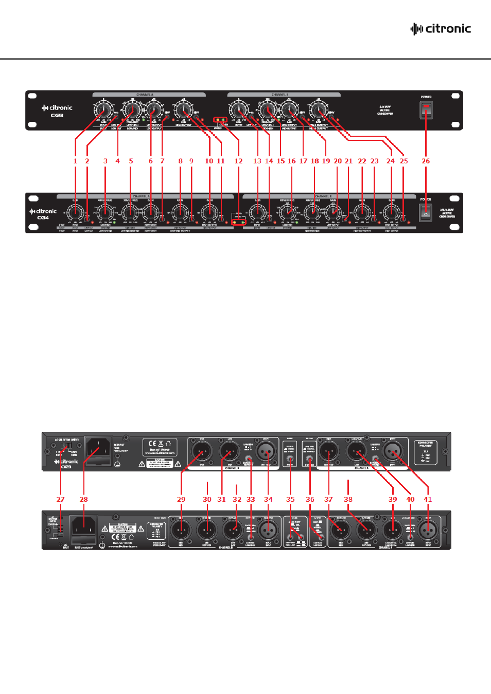
Front Panel
Rear Panel
14.
Low Cut filter: Channel B
15.
Low/High - Mid/High crossover Frequency: Channel B
16.
Low/High - Low/Mid crossover Frequency: Channel B
17.
Low or Mid output gain: Channel B
18.
Mid/High - High-mid/High crossover frequency: Ch B
19.
Low or Mid output phase switch: Channel B
20.
Low output gain: Channel B
21.
Low output phase switch: Channel B
22.
Mid or High-mid output gain: Channel B
23.
Mid or High-mid output phase switch: Channel B
24.
High output gain: Channel B
25.
High output phase switch: Channel B
26.
Power switch
1. Input gain: Channel A
2. Low Cut filter: Channel A
3. Low/High X-over Frequency: Channel A
4. Low/High - Low/Mid crossover Frequency: Channel A
5. Low/Mid - Mid/High crossover Frequency: Channel A
6. Low output gain: Channel A
7. Low output phase switch: Channel A
8. Mid or Low-mid output gain: Channel A
9. Mid or Low-mid output phase switch: Channel A
10. High output gain: Channel A
11. High output phase switch: Channel A
12. Mono/Stereo mode indicators
13. Input gain: Channel B
27. Voltage selector
28. IEC mains inlet
29. High output: Channel B
30. High-mid or Mid output: Channel B
31. Low or Mid output: Channel B
32. Low output: Channel B
33. Crossover frequency multiplier: Channel B
34. Input: Channel B
35. Mode selector buttons
36. Mono Normal/Summed switch
37. High output: Channel A
38. Low-mid or Mid output: Channel A
39. Low output: Channel A (or LF Sum both channels)
40. Crossover frequency multiplier: Channel A
41. Input: Channel A