Analytical Industries GPR-2500 S Oxygen Analyzer User Manual
Page 14
14
When used in conjunction with the optional MTL 702, third party certified, intrinsic safety barriers, the design of
the GPR-2500S Ambient Oxygen Monitors meet recognized standards as intrinsically safe for operation in Class I,
II, III; Division I, II; Groups A-G hazardous areas.
Note: Locate the optional intrinsic safety barrier as close to the power source in the non-hazardous area as
possible.
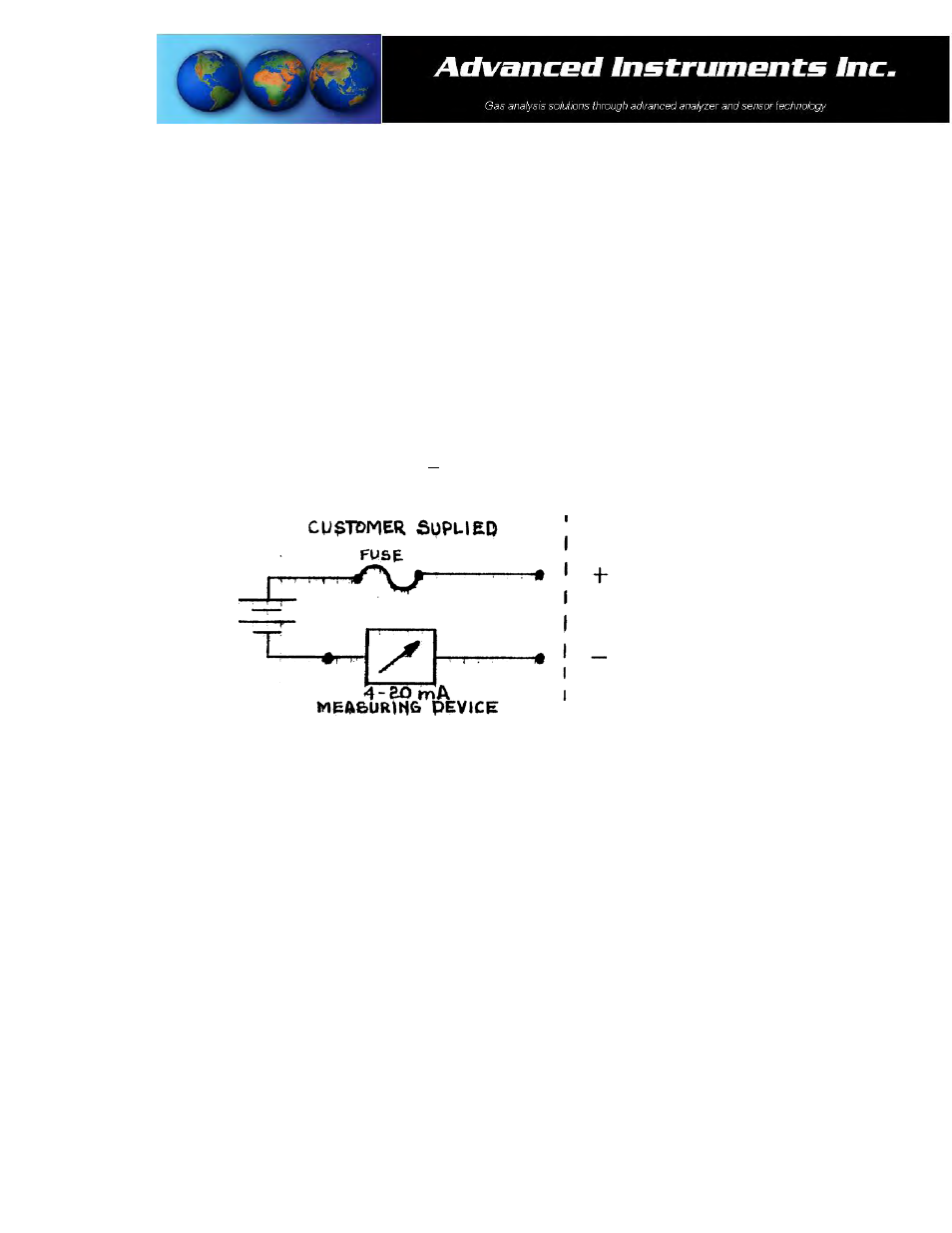
Output connection:
The 4-20mA current output is obtained by connecting the current measuring device between the negative terminal
of power source and the negative terminal, marked (-), located in the junction box of the monitors. The positive
current flow is from pin 1 to pin 2 and from pin 2 to ground through the external load.
To check the signal output of the 4-20mA E/I integrated circuit connect an ammeter, as illustrated below, as the
measuring device and confirm the output is within +0.1mA of 4mA.
Power 12-36V DC
To Monitors
Terminal Strip
Caution: To assure proper grounding, connect the 4-20mA signal output to the external device (PLC, DCS, etc.)
before attempting any zero or span adjustments.