Gas connections – Analytical Industries GPR-2500 S Oxygen Analyzer User Manual
Page 11
11
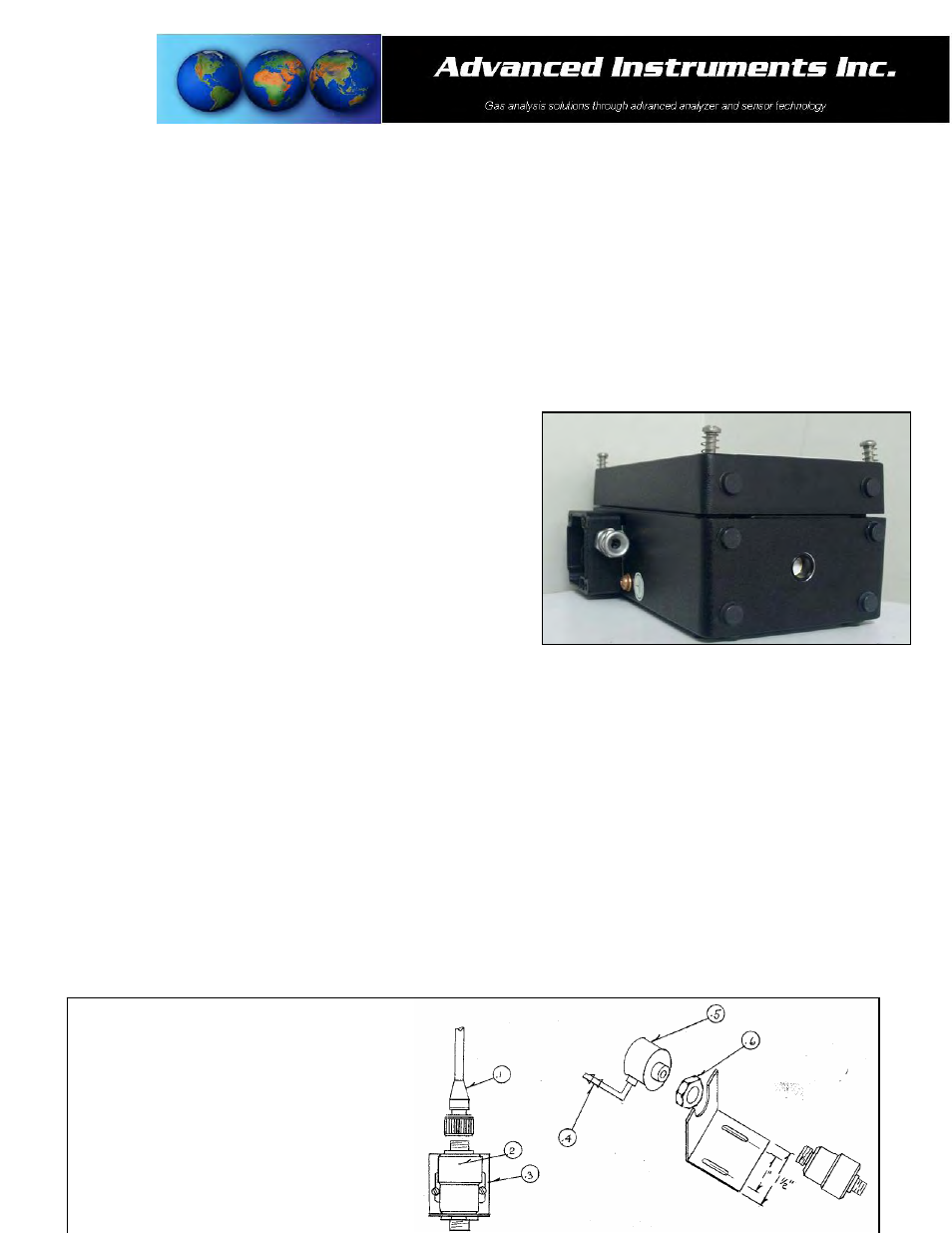
5. The monitors design provides protection from RFI that is maintained by leaving specific mating areas of the
enclosure unpainted to maintain conductivity the gasket, top and bottom sections of the enclosure. These
unpainted areas are protected by gaskets and contribute to maintaining the NEMA 4 rating. Do not paint these
areas. Painting will negate the RFI protection.
6. As described below the power connection is made through the junction box on the left side of the enclosure.
Gas Connections:
As described above, the sensor in the GPR-2500S ambient monitor configuration is exposed directly to ambient air
through the bottom section of the enclosure and designed to continuously monitor the oxygen content in the
atmosphere of the surrounding area, confined spaces and control rooms where the potential for a lethal deficiency
of oxygen exists.
For calibration, the user is responsible for calibration gases and
the required components, see Span Gas Preparation below,
supplying an adequate amount of Tygon tubing to pipe the span
gas to the flow through adaptor, regulating the pressure of the
span gas between 5-30 psig and controlling the flow rate to
approximately 2 SCFH or 1 liter per minute.
Caution: Do not place your finger over the vent (it pressurizes
the sensor) to test the flow indicator when gas is flowing to the
sensor. Removing your finger (the restriction) generates a
vacuum on the sensor and may damage the sensor (voiding the
sensor warranty).
Calibration Gas Connections – Integral and Remote Sensor:
1. Caution: Do not change the factory setting until instructed to do in this manual.
2. Review the illustration below and locate Item A-2344 Calibration Flow Through Adapter and the installed Item
FITN-1029 Connector, Barbed Tubing.
3. Review Span Gas Preparation section below – regulate the pressure and control the flow rate as directed.
4. Caution: When configured for ambient monitoring of oxygen deficiency in a confined space or room do not
calibrate the unit in the atmosphere to be monitored. Use a certified span gas of a known oxygen
concentration approximating 20.9% oxygen balance nitrogen or clean compressed air.
5. Apply a little lubricant to the o-ring, a dry o-ring can make insertion difficult, of the Calibration Flow Through
Adapter Assembly, A-2344.
6. Insert the flow through adapter into the throat of the sensor.
7. Connect the 1/8” ID Tygon tubing from the flow meter vent to Item #4 Connector, Barbed Tubing.
8. Proceed to Span Calibration section.
Legend:
1. CONN-1014 Sensor Cable
2. GPR-11-32-4R Oxygen Sensor
3. A-2079 Bracket Sensor Mounting