Electrical connections – Analytical Industries GPR-2500 S Oxygen Analyzer User Manual
Page 12
12
4. FITN-1029 Connector, Barbed Tubing
5. A-2344 Calibration Flow Through Adapter
(Calibration use only)
6. A-2781 Nut Sensor Retaining
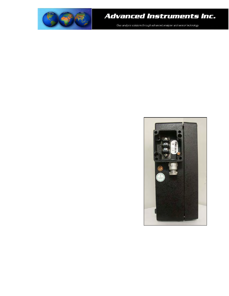
Electrical Connections
Remove the front cover of the junction box located on left side of the monitors by removing the four (4) screws
securing the cover and set them aside for reinstallation.
To assure proper grounding, connect the 4-20mA signal output to the external device (PLC, DCS, etc.) before
attempting any zero or span adjustments.
Power requirements consist of a two wire shielded cable and a 12-36V DC with negative ground power supply.
Procedure:
1. Loosen the nut on the cable gland.
2. Separate the shielding from the wires of the cable.
3. Thread the wires through the cable gland into the inside of the
junction box.
4. Connect the two wires to the two (2) screw type terminals of the
barrier strip inside the junction box.
5. Ensure the positive and negative terminals of the power supply are
connected to the appropriate terminals of the barrier strip as
marked.
6. Connect the shielding of the cable to the copper ground screw inside
the junction box.
7. Replace the junction box cover ensuring the gaskets are in place and
tighten the four (4) screws.
8. Tighten the cable gland to maintain NEMA 4 rating.
Hazardous Area Installation:
The GPR-2500S monitors may be installed in a hazardous area with
specific intrinsic safety barriers and a barrier enclosure approved for use
with the safety barrier selected.
MTL 702 type barriers and a 24VDC power supply with two (2) wire shielded cable are recommended.
Requirements include a 4-20mADC two (2) wire signal and a power requirement of 20mADC per channel at 24VDC
minimum.
The following chart identifies the required wire based on the distance from the safety barriers to the two wire
monitors.
4,500 ft. – 22 AWG
7,200 ft. – 20 AWG
11,500 ft. – 18 AWG