Analytical Industries GPR-1100 ATEX Portable Trace PPM Oxygen Analyzer User Manual
Page 13
13
Gas Connections:
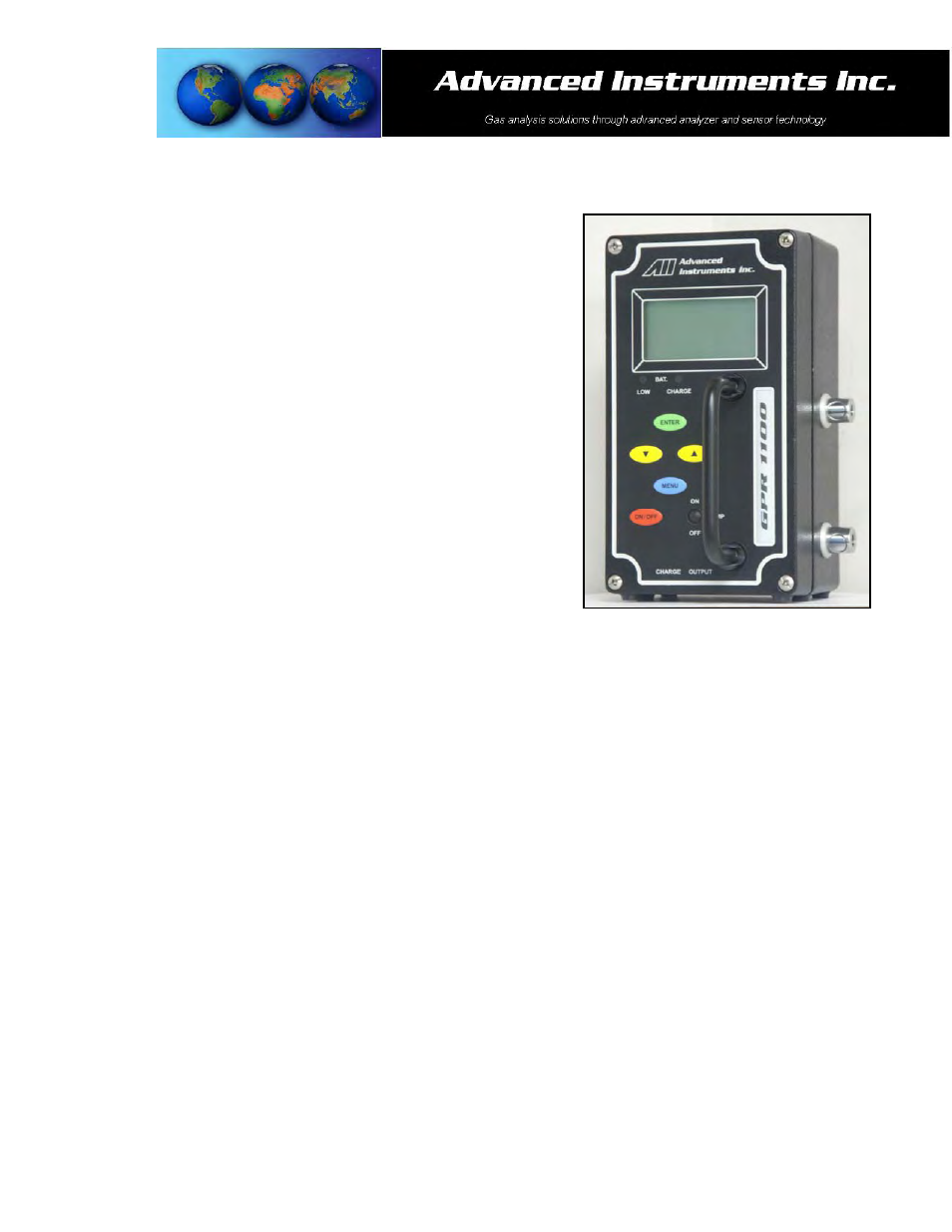
The GPR-1100 flow through configuration is designed for positive
pressure samples and requires connections to incoming sample and
vent female quick disconnect fittings. The user is responsible for
making provision for introducing gases for calibration purposes.
Flow rates of 1-5 SCFH cause no appreciable change in the oxygen
reading. However, flow rates above 5 SCFH generate backpressure
and erroneous oxygen readings because the diameter of the integral
tubing cannot evacuate the sample gas at the higher flow rate.
A flow indicator with an integral metering valve upstream of the sensor
is recommended as a means of controlling the flow rate of the sample
gas. A flow rate of 2 SCFH or 1 liter per minute is recommended for
optimum performance.
Caution: Do not place your finger over the vent (it pressurizes the
sensor) to test the flow indicator when gas is flowing to the sensor.
Removing your finger (the restriction) generates a vacuum on the
sensor and may damage the sensor (voiding the sensor warranty).
To avoid generating a vacuum on the sensor (as described above)
during operation, always select and install the vent fitting first and
remove the vent fitting last.
Procedure:
1. Caution: Do not change the factory setting until instructed.
2. Designate the female quick disconnect fittings, right side of the analyzer, as inlet and vent respectively.
3. Regulate the pressure and flow as described in Pressure & Flow above.
4. Install one mating male vent fitting into the female quick disconnect fitting designated as the VENT –
connection of 1/8” dia. metal vent line (requires an 1/8” male NPT to tube adapter) is optional.
5. Connect the second mating male fitting to 1/8” dia. metal sample line using a 1/8” male NPT to tube adapter.
6. Connect the third mating male fitting to 1/8” dia. metal span gas line using a 1/8” male NPT to tube adapter.
7. Install either the sample or span mating male fitting into the female quick disconnect fitting designated as
SAMPLE.
8. Set the flow rate to 2 SCFH (open the flow control valve completely if using an external sampling pump
positioned downstream of the sensor).
9. Allow gas to flow through the analyzer for 3-5 minutes and proceed to Calibration or Sampling.