Analytical Industries GPR-1200 ATEX Portable Trace PPM Oxygen Analyzer User Manual
Page 23
23
30. Disconnect the span gas line.
31. Connect a purge gas line of either zero or sample gas with a low oxygen concentration.
32. Allow the purge gas to flow for 1-2 minutes to purge the air trapped in the span gas line.
33. Place the SAMPLE/BYPASS valve in the SAMPLE position.
34. Allow the purge gas to flow in order to purge the sensor of the oxygen trapped inside from the calibration gas and bring
the analyzer online to desired the measurement range.
35. Caution: Wait until the reading is stable before proceeding with sampling. The wait time will vary depending on
the amount oxygen introduced to the sensor during calibration and/or when the gas lines were switched.
36. Once the reading is stable, place the SAMPLE/BYPASS valve in the BYPASS position.
37. Disconnect the purge gas line.
38. Connect the sample gas line.
39. Allow the sample gas to flow for 1-2 minutes to purge the air trapped in the sample gas line.
40. Place the SAMPLE/BYPASS valve in the SAMPLE position.
41. Wait until the reading is stable and proceed to sampling.
Procedure Air Calibration – Without Integral Pump:
1. Review the above Span Calibration procedure and the following instructions before proceeding:
(a) Range selection and menu operation – note steps #7-9, #29-30 and #32-33 do not apply.
(b) Section 6 Maintenance – instructions for removing the sensor explain how to expose the sensor to ambient air.
2. Access the interior of the analyzer by removing the four (4) screws securing the front panel of the analyzer.
3. Caution: Do not remove the gaskets from the enclosure. Failure to reinstall the gasket will void the NEMA rating.
4. Remove the sensor from the sensor housing as described in section 6 Maintenance.
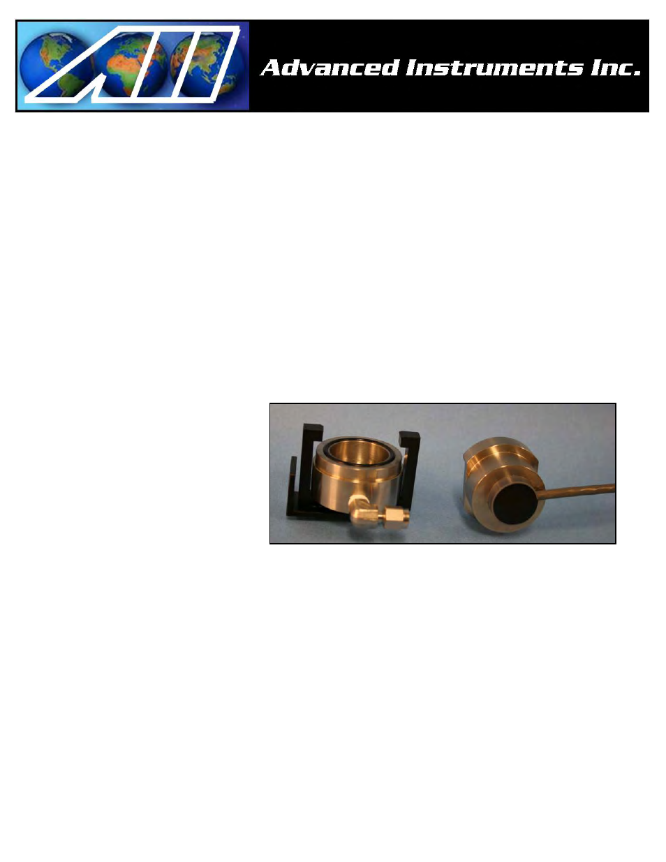
5. Hold the sensor and upper sensor housing
with cable between your thumb and first
two fingers.
6. The thumb should be on the front of the
sensor and to the side – do not cover
sensing area.
7. Ensure the PCB at the rear of the sensor
makes contact with the pins inside the
sensor housing with the connecting cable
and rest the back of the sensor housing
with the connecting cable against the first
two fingers.
8. With the sensor exposed to ambient air in
the manner described above – resume the procedure and perform steps #10-28.
9. Reinstall the sensor as described in section 6 Maintenance.
10. Remember steps #29-30 and #32-33 do not apply because for air calibration the SAMPLE/BYPASS valve should already be
in the SAMPLE position.
11. Perform step #31.
12. Skip to step #34 and perform the remainder of the procedure.
13. Replace the front cover of the analyzer and ensure that the gasket is replaced to maintain CE approval and NEMA 4 rating.
14. Tighten the four (4) screws to secure the front cover.
Procedure Air Calibration – with Integral Pump:
1. Review the above Span Calibration procedure and the following instructions before proceeding:
(a) Range selection and menu operation – note steps #6-10, #29-30 and #32-33 do not apply.
2. Select a source of good ambient air.
3. Ensure the step #5 is performed and the SAMPLE/BYPASS valve is in the SAMPLE position.
4. Open the FLOW VALVE completely – to prevent the pump from drawing a vacuum on the sensor.
5. Disconnect any tubing connected to the inlet fitting located on the left side of the analyzer.
6. Toggle the PUMP ON/OFF switch to the ON position to operate the integral sampling pump and draw the ambient air span
gas into the analyzer.
7. With the integral pump operating – resume the above procedure and perform steps #10-28.