Advanced instruments inc, Sampling – Analytical Industries GPR-28 Oxygen Analyzer User Manual
Page 27
Advanced Instruments Inc.
27
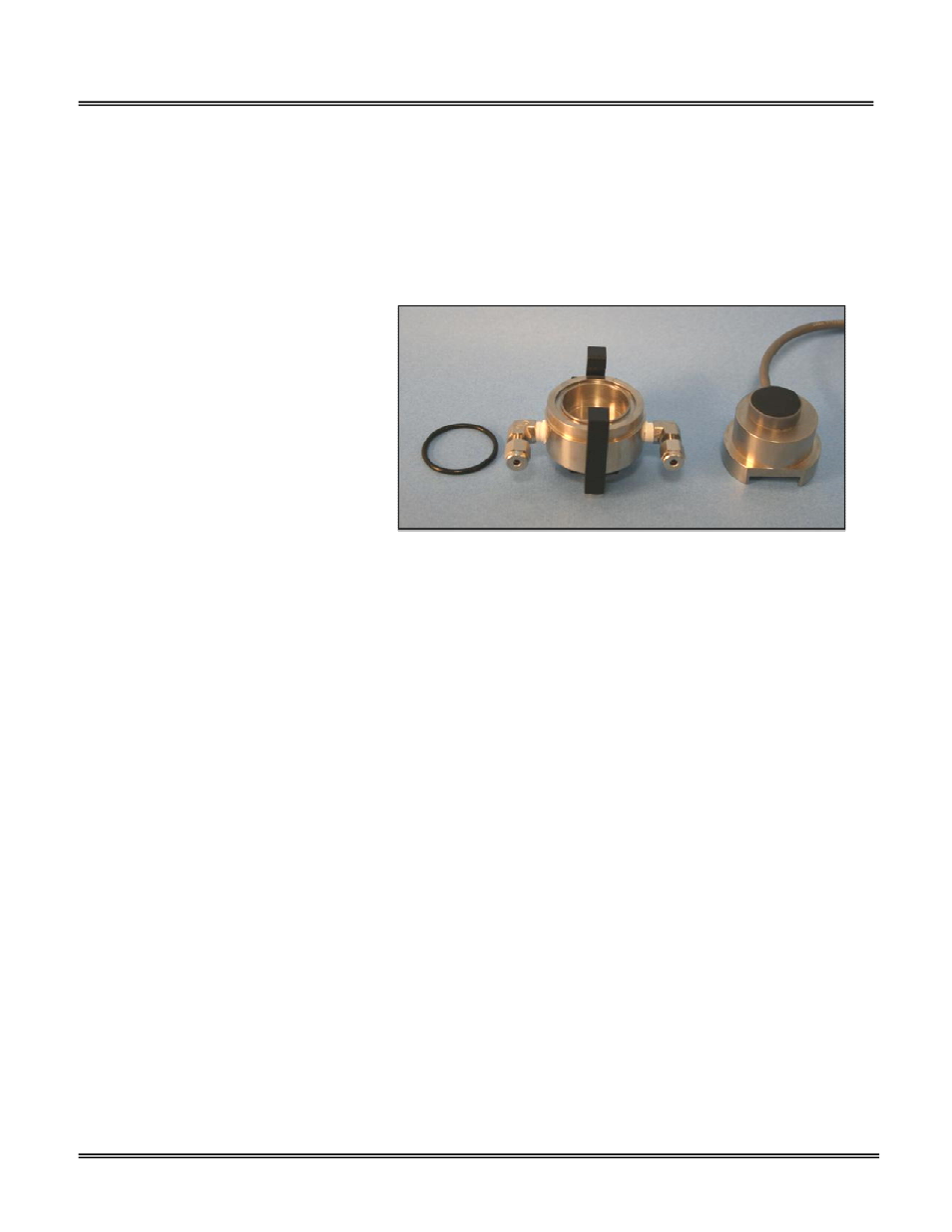
7. With your other hand remove the oxygen sensor, place it in the upper section of the sensor housing ensuring the PCB
contacts the two gold pins and use your thumb to hold the sensor and upper section of the sensor housing together.
8. The sensor is now exposed to ambient air, connected to the analyzer electronics and ready for calibration.
9. With the sensor exposed to ambient air – allow the reading to stabilize before adjusting the SPAN actuator/potentiometer.
10. After the reading stabilizes, turn the SPAN actuator/potentiometer ½ turn at a time until the LED display reads the 20.9
oxygen content of ambient air.
11. Caution: Turning the actuator/potentiometer more the ½ turn recommended does not allow the electronics sufficient time
to keep pace with the adjustment. And
since adjustments are rarely made in one
consecutive turn – there is a real possibility
that the 2
nd
and 3
rd
part of the adjustment
could unknowingly be based on “values that
have not stabilized” thereby resulting in an
inaccurate calibration.
12. Reinstall the sensor as follows:
13. Place the sensor in the bottom section of
the sensor housing with the PCB facing up.
14. Place the upper section of the sensor
housing over the sensor.
15. Gently push the upper section downward
and rotate 90º to engage the clamp.
16. Finger tighten the clamp bolt and one full turn with the 5/16 wrench to compressed the o-ring seal.
17. Note: Manually turn the RANGE selector switch to follow the progress of the sensor’s recovery from exposure to air during
installation.
18. Begin sampling once the analyzer has reached the value of the purge gas.
Sampling
The sensor is exposed to sample gas that must flow or be drawn through the analyzer’s internal sample system. To ensure your
applications and gas sample are consistent with your expectations, review the Installation considerations in section 3.
Pico-Ion MS sensor: Slightly more sensitive to changes in flow rates but changes of 1-3 SCFH cause no appreciable change in
the oxygen reading. However, higher flow rates and/or sudden changes in flow rates can cause erratic readings or even
damage the sensor. A FLOW valve upstream of the sensor controls the flow rate of the sample gas which is displayed by the
flow indicator downstream of the sensor. A flow rate of 1 SCFH is recommended for optimum performance.
Galvanic ppm sensor: Flow rates of 1-5 SCFH cause no appreciable change in the oxygen reading. However, flow rates above 5
SCFH can generate erroneous oxygen readings. A FLOW valve upstream of the sensor controls the flow rate of the sample gas
which is displayed by the flow indicator downstream of the sensor. A flow rate of 2 SCFH is recommended for optimum
performance.
Galvanic percent sensors: Flow rates of 1-5 SCFH cause no appreciable change in the oxygen reading. However, flow rates
above 5 SCFH can generate erroneous oxygen readings. A FLOW METER with integral metering valve upstream of the sensor
controls the flow rate of the sample gas and displays the flow rate. A flow rate of 2 SCFH is recommended for optimum
performance.
Application Pressure - Positive:
A FLOW valve positioned upstream of the sensor controls the sample flow rate to the recommended flow rate. If necessary, a
pressure regulator (with a metallic diaphragm is recommended for optimum accuracy, the use of diaphragms of more
permeable materials may result in erroneous readings) upstream of the flow control valve should be used to regulate the inlet
pressure as specified in section 4.