Advanced instruments inc, Mounting the analyzer & sensor – Analytical Industries GPR-1900 Series Trace PPB Oxygen Analyzer User Manual
Page 12
Advanced Instruments Inc.
12
Recommendations to avoid erroneous oxygen readings and damaging the sensor:
¾ Do not place your finger over the vent (it pressurizes the sensor) to test the flow indicator when gas is flowing to the
sensor. Removing your finger (the restriction) generates a vacuum on the sensor and may damage the sensor (voiding the
sensor warranty).
¾ Assure there are no restrictions in the sample or vent lines
¾ Avoid drawing a vacuum that exceeds 14” of water column pressure – unless done gradually
¾ Avoid excessive flow rates above 5 SCFH which generate backpressure on the sensor.
¾ Avoid sudden releases of backpressure that can severely damage the sensor.
¾ Avoid the collection of liquids or particulates on the sensor, they block the diffusion of oxygen into the sensor.
¾ If the analyzer is equipped with an optional integral sampling pump (positioned downstream of the sensor) and a flow
control metering valve (positioned upstream of the sensor), completely open the flow control metering valve to avoid
drawing a vacuum on the sensor and placing an undue burden on the pump.
Moisture & Particulates: Installation of a suitable coalescing or particulate filter is required to remove condensation, moisture
and/or particulates from the sample gas to prevent erroneous analysis readings and damage to the sensor or optional
components. Moisture and/or particulates do not necessarily damage the sensor, however, collection on the sensing surface can
block or inhibit the diffusion of sample gas into the sensor resulting in a reduction of sensor signal output – and the appearance
of a sensor failure when in fact the problem is easily remedied by blowing on the front of the sensor. Consult the factory for
recommendations concerning the proper selection and installation of components.
Gas Connections: Inlet and outlet vent gas lines for ppm analysis require 1/8” or ¼” stainless steel compression fittings; hard
plastic tubing with a low permeability factor can be used percentage range measurements.
Power Connection: Locate the appropriate source of to meet the analyzer or analyzer requirements, ensure that is properly
grounded and meets the area classification.
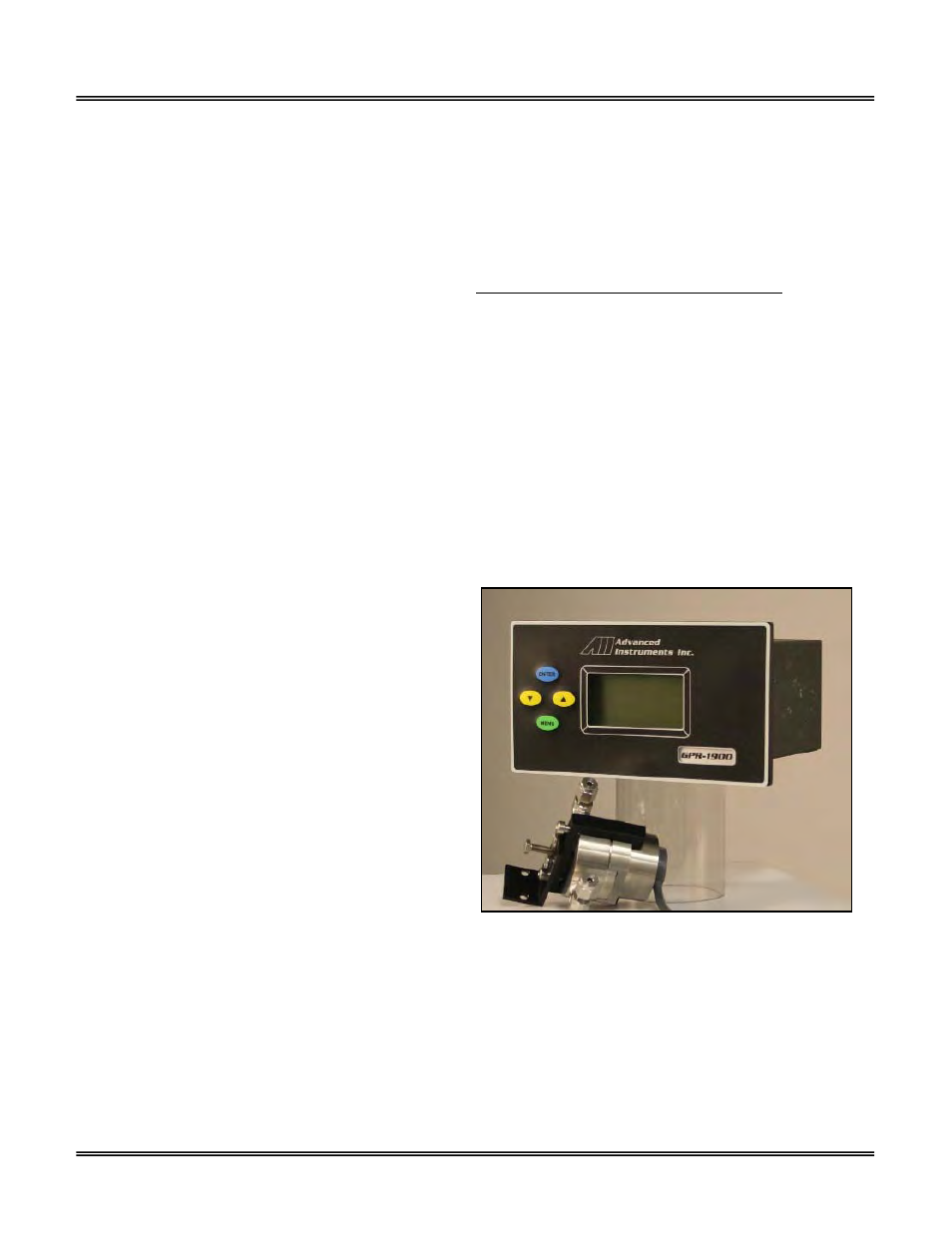
Mounting the Analyzer & Sensor
The GPR-1900 consists of a six (6) foot insulated cable which
connects the sensor to the rear of the electronics module, a
long life maintenance free oxygen sensor and a stainless steel
sensor housing equipped with 1/8” diameter stainless steel
compression fittings.
The compact design also lends itself to optional mounting
configuration such as a standard 19” rack or wall mount
enclosures, both of which can be equipped with optional
sample system components. Contact the factory for additional
information.
Procedure:
1. The GPR-1900 front panel measures 7”W x 4”H x 4.5”D.
This compact configuration is designed for panel
mounting directly to any flat vertical surface, wall or
bulkhead plate with the appropriate 6”W x 3”H cut out
and four ¼” diameter holes for insertion of the mounting studs located on the back side of the front panel.
2. When mounting the analyzer position it approximately 5 feet off the floor for viewing purposes and allow sufficient room for
access to the terminal connections at the rear of the enclosure.
3. Note: The proximity of the analyzer to the sample point and use of optional sample conditioning components have an
impact on sample lag time.
4. Position the sensor housing along any flat surface. The bracket attached to the sensor housing is fabricated with two 6/32
mounting holes. The oxygen sensor is not position sensitive but it is recommended to orient the sensor housing with the
upper section identified by the interconnection cable facing the ceiling.
5. Connect the four wires of the cable, following the color coding above the terminal block, at the rear of the analyzer.
6. Attach the flow housing to the mounting position determine above.
7. Do not install the sensor at this time, see below.