Asus Vintage User Manual
Page 51
A S U S V i n t a g e - S 8 0 0
A S U S V i n t a g e - S 8 0 0
A S U S V i n t a g e - S 8 0 0
A S U S V i n t a g e - S 8 0 0
A S U S V i n t a g e - S 8 0 0
4 - 7
4 - 7
4 - 7
4 - 7
4 - 7
2 .
2 .
2 .
2 .
2 .
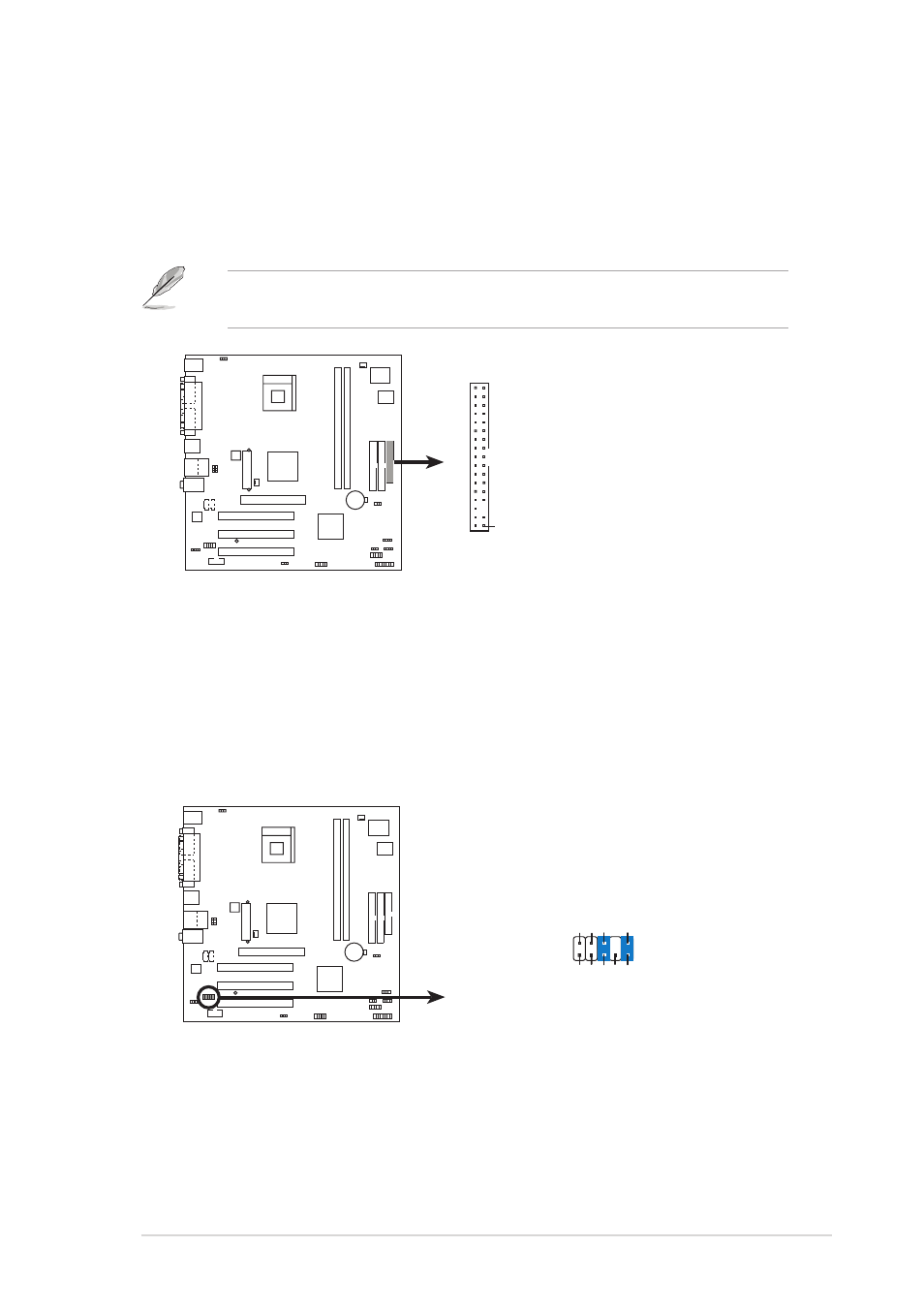
F l o p p y d i s k d r i v e c o n n e c t o r ( 3 4 - 1 p i n F L O P P Y 1 )
F l o p p y d i s k d r i v e c o n n e c t o r ( 3 4 - 1 p i n F L O P P Y 1 )
F l o p p y d i s k d r i v e c o n n e c t o r ( 3 4 - 1 p i n F L O P P Y 1 )
F l o p p y d i s k d r i v e c o n n e c t o r ( 3 4 - 1 p i n F L O P P Y 1 )
F l o p p y d i s k d r i v e c o n n e c t o r ( 3 4 - 1 p i n F L O P P Y 1 )
This connector is for the provided floppy disk drive (FDD) signal cable.
Insert one end of the cable to this connector, then connect the other
end to the signal connector at the back of the floppy disk drive.
Pin 5 on the connector is removed to prevent incorrect cable connection
when using a FDD cable with a covered Pin 5.
3 .
3 .
3 .
3 .
3 .
F r o n t p a n e l a u d i o c o n n e c t o r s ( 1 0 - 1 p i n F P _ A U D I O 1 )
F r o n t p a n e l a u d i o c o n n e c t o r s ( 1 0 - 1 p i n F P _ A U D I O 1 )
F r o n t p a n e l a u d i o c o n n e c t o r s ( 1 0 - 1 p i n F P _ A U D I O 1 )
F r o n t p a n e l a u d i o c o n n e c t o r s ( 1 0 - 1 p i n F P _ A U D I O 1 )
F r o n t p a n e l a u d i o c o n n e c t o r s ( 1 0 - 1 p i n F P _ A U D I O 1 )
This connector is for a chassis-mounted front panel audio I/O module.
Connect one end of the audio I/O module cable to this connector for
analog audio input/output.
NOTE: Orient the red markings on
the floppy ribbon cable to PIN 1.
Floppy disk drive connector
PIN 1
FLOPPY1
Front panel audio connector
FP_AUDIO1
BLINE_OUT_L
MIC2
Line out_R
Line out_L
BLINE_OUT_R
NC
MICPWR
+5V
A
AGND