4 internal components – Asus Vintage User Manual
Page 16
C h a p t e r 1 : S y s t e m i n t r o d u c t i o n
C h a p t e r 1 : S y s t e m i n t r o d u c t i o n
C h a p t e r 1 : S y s t e m i n t r o d u c t i o n
C h a p t e r 1 : S y s t e m i n t r o d u c t i o n
C h a p t e r 1 : S y s t e m i n t r o d u c t i o n
1 - 6
1 - 6
1 - 6
1 - 6
1 - 6
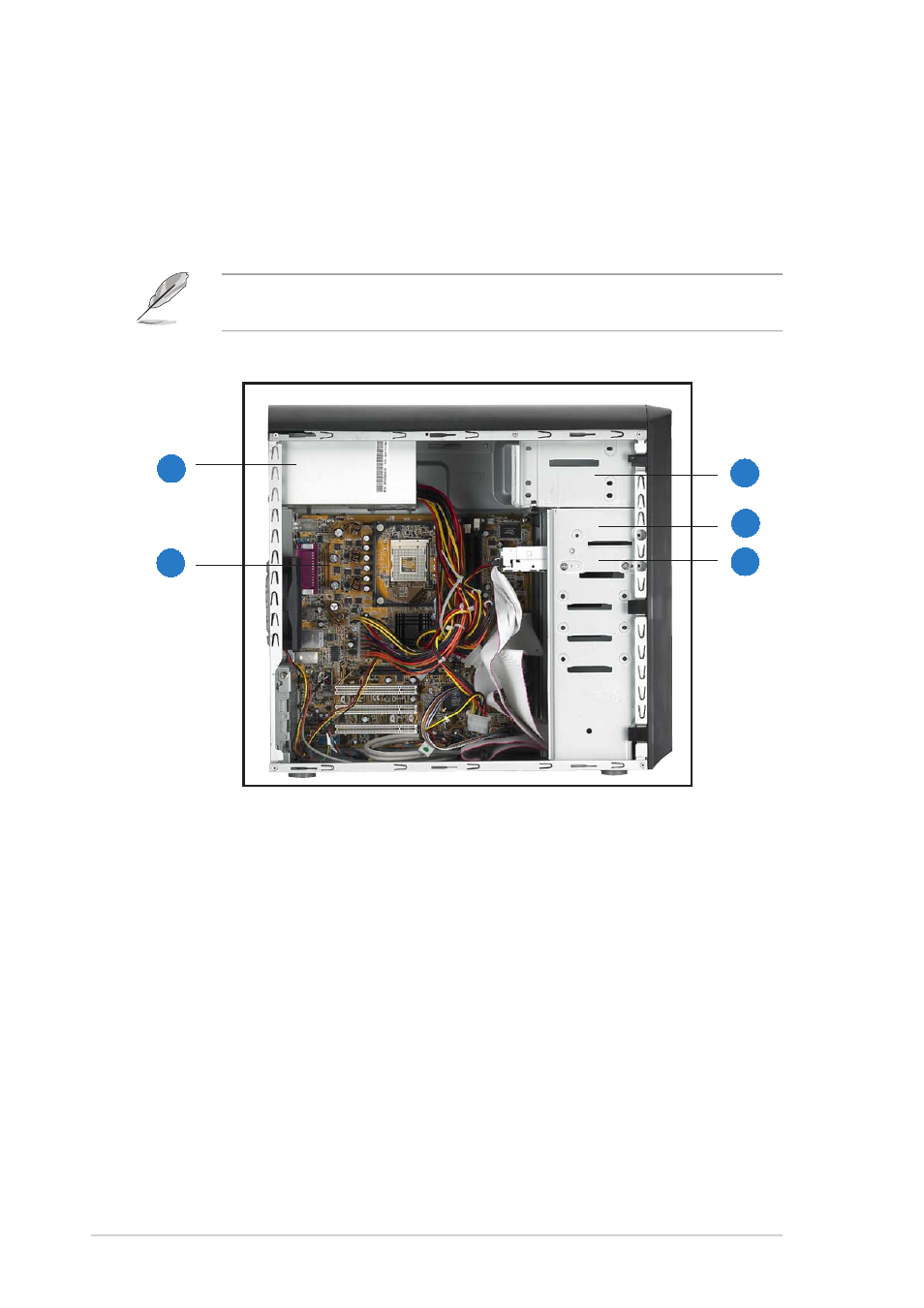
1.4
Internal components
The figure below shows the internal view of the system when you remove
the cover and flip out the drive frame. The standard components already
installed in the system and the locations of the available drive bays are
pointed out.
The system may come with either a PFC (Power Factor Correction) or
non-PFC power supply.
4.
3.5” HDD drive bay
5.
3.5” Floppy drive bay
(drive in photo not included)
1.
PFC/Non-PFC power supply
2.
Motherboard
3.
Two 5.25” optical drive bays
1
1
1
1
1
2
2
2
2
2
3
3
3
3
3
4
4
4
4
4
5
5
5
5
5
- CG8565 (410 pages)
- CG8565 (246 pages)
- CS5111 (26 pages)
- CS5120 (1 page)
- ET1611PUK (38 pages)
- S2-P8H61E (80 pages)
- P2-PH1 (80 pages)
- P1-P5945G (80 pages)
- P2-P5945GCX (90 pages)
- CG8270 (72 pages)
- CG8270 (76 pages)
- CG8270 (534 pages)
- CG8270 (362 pages)
- CG8270 (218 pages)
- CG8270 (536 pages)
- P3-P5G31 (100 pages)
- P3-PH4 (80 pages)
- P2-M2A690G (80 pages)
- P2-M2A690G (8 pages)
- P4-P5N9300 (82 pages)
- P4-P5N9300 (1 page)
- P1-P5945GC (92 pages)
- P2-P5945GC (92 pages)
- P3-P5G33 (98 pages)
- T3-P5945GCX (80 pages)
- T3-P5945GC (80 pages)
- P2-M2A690G (94 pages)
- T3-PH1 (80 pages)
- T3-PH1 (82 pages)
- T5-P5G41E (76 pages)
- T5-P5G41E (82 pages)
- S1-AT5NM10E (68 pages)
- P6-P7H55E (67 pages)
- ES5000 (174 pages)
- T4-P5G43 (104 pages)
- T-P5G31 (92 pages)
- BT6130 (2 pages)
- BT6130 (60 pages)
- BT6130 (54 pages)
- CG8265 (350 pages)
- CG8265 (210 pages)
- CM1740 (198 pages)
- CM1740 (330 pages)
- CM1740 (70 pages)
- P6-M4A3000E (59 pages)