Asus b85m-k – Asus B85M-K User Manual
Page 27
ASUS B85M-K
1-19
9.
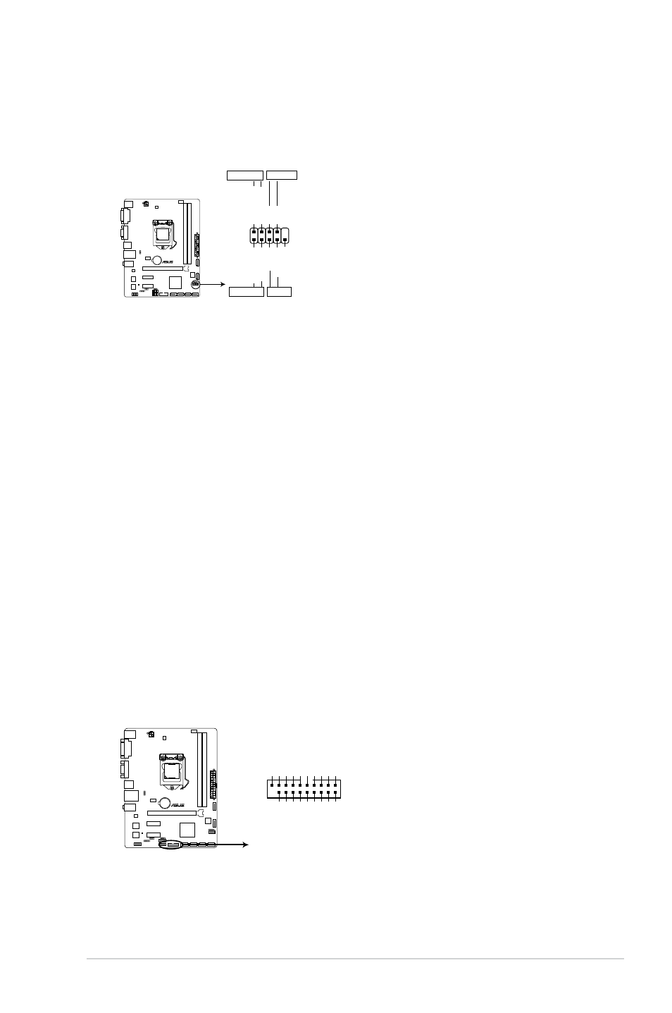
System panel connector (10-1 pin F_PANEL)
This connector supports several chassis-mounted functions.
B85M-K
B85M-K System panel connector
PIN 1
PWR_BTN
PWR_LED+
PWR_LED-
PWR GND
HDD_LED+ HDD_LED-
Ground
HWRST#
(NC)
F_PANEL
+PWR_LED-
+HDD_LED- RESET
•
System power LED (2-pin PWR_LED)
This 2-pin connector is for the system power LED. Connect the chassis power LED
cable to this connector. The system power LED lights up when you turn on the system
power, and blinks when the system is in sleep mode.
•
Hard disk drive activity LED (2-pin HDD_LED)
This 2-pin connector is for the HDD Activity LED. Connect the HDD Activity LED cable
to this connector. The HDD LED lights up or flashes when data is read from or written
to the HDD.
•
ATX power button/soft-off button (2-pin PWR_BTN)
This connector is for the system power button.
•
Reset button (2-pin RESET)
This 2-pin connector is for the chassis-mounted reset button for system reboot without
turning off the system power.
10. USB 3.0 connector (20-1 pin USB3_910)
These connectors allow you to connect a USB 3.0 module for additional USB 3.0 front
or rear panel ports. With an installed USB 3.0 module, you can enjoy all the benefits of
USB 3.0 including faster data transfer speeds of up to 5Gbps, faster charging time for
USB-chargeable devices, optimized power efficiency and backward compatibility with
USB 2.0.
USB3_910
USB3+5V IntA_P1_SSRX- IntA_P1_SSRX+ GND IntA_P1_SSTX- IntA_P1_SSTX+ GND IntA_P1_D- IntA_P1_D+ GND
PIN 1
USB3+5V
IntA_P2_SSRX- IntA_P2_SSRX+
GND
IntA_P2_SSTX- IntA_P2_SSTX+
GND
IntA_P2_D- IntA_P2_D+
B85M-K
B85M-K USB3.0 Front panel connector