2 internal connectors, 2 internal connectors -20, F1a55-v digital audio connector – Asus F1A55-V User Manual
Page 32: F1a55-v fan connectors, Chapter 1: product introduction 1-20
1.10.2
Internal connectors
1.
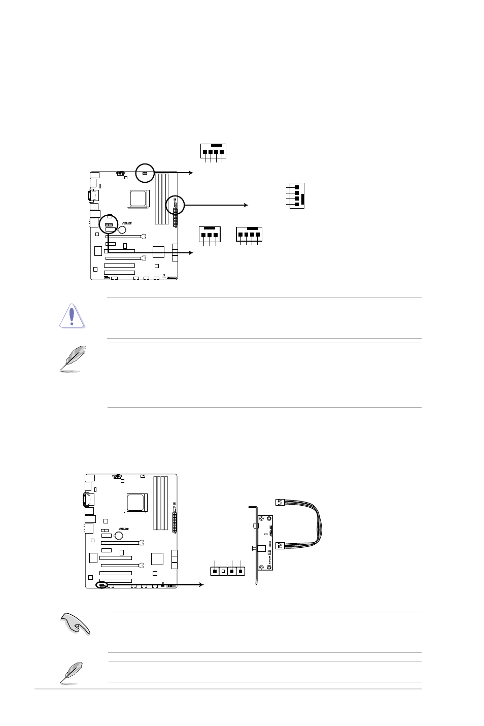
Power, CPU and chassis fan connectors (3-pin PWR FAN, 4-pin CPU_FAN, and
4-pin CHA_FAN 1/2)
Connect the fan cables to the fan connectors on the motherboard, ensuring that the
black wire of each cable matches the ground pin of the connector.
• The CPU_FAN connector supports a CPU fan of maximum 2A (24 W) fan power.
• Only the CPU_FAN and CHA_FAN 1/2 connectors support the ASUS Fan Xpert feature.
• If you install two VGA cards, we recommend that you plug the rear chassis fan cable to
the motherboard connector labeled CHA_FAN 1/2 for better thermal environment.
DO NOT forget to connect the fan cables to the fan connectors. Insufficient air flow inside
the system may damage the motherboard components. These are not jumpers! DO NOT
place jumper caps on the fan connectors.
F1A55-V
F1A55-V fan connectors
CPU_FAN
CHA_FAN2
CPU F
AN PWM
CPU
FA
N IN
CPU
FA
N PW
R
GND
CHA_FAN1
CHA
F
A
N PW
M
CHA
F
A
N IN
CHA
F
A
N PW
R
GND
CHA FAN PWM
CHA FAN IN
CHA FAN PWR
GND
Rotation
+12V GN
D
PWR_FAN
2.
Digital audio connector (4-1 pin SPDIF_OUT)
This connector is for an additional Sony/Philips Digital Interface (S/PDIF) port.
Ensure that the audio device of Sound playback is Realtek High Definition Audio (the
name may be different based on the OS). Go to Start > Control Panel > Sounds and
Audio Devices > Sound Playback to configure the setting.
The S/PDIF module is purchased separately.
SPDIF_OUT
+5
V
SPDIFOU
T
GND
F1A55-V
F1A55-V Digital audio connector
Chapter 1: Product introduction
1-20