Installazione della cpu, Diagramma disposizione scheda madre, Italiano – Asus P4P800S SE User Manual
Page 8: Scheda madre asus p4p800s se, Pci1, Pci2 pci3 pci4 pci5, Panel1
8
Scheda madre ASUS P4P800S SE
Italiano
2.
Installazione della CPU
Attenersi alle fasi seguenti per installare una CPU.
1. Ubicare la presa ZIF a 478 pin sulla scheda madre.
2. Sollevare la leva della presa ad un angolo di almeno 90°.
1.
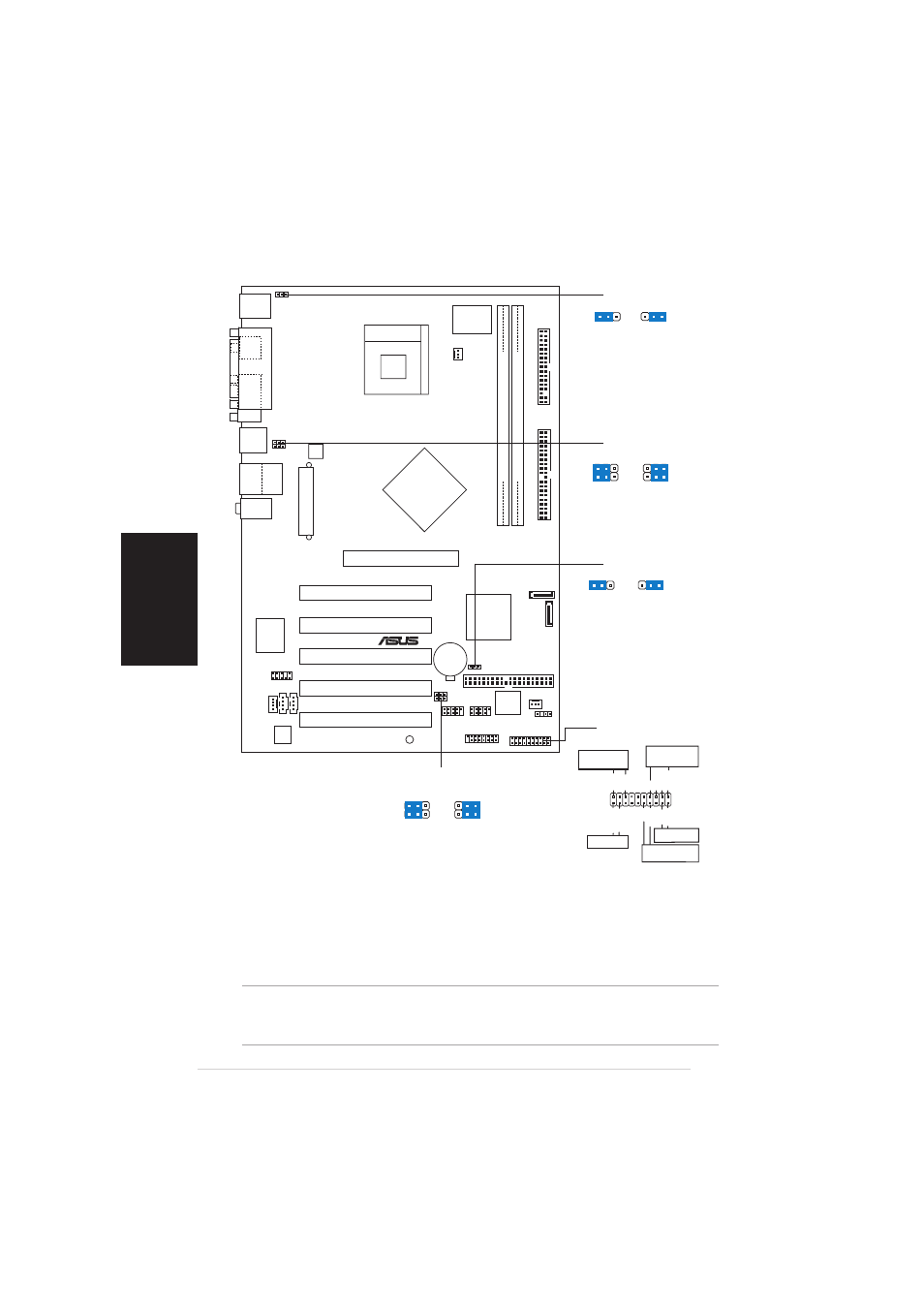
Diagramma disposizione scheda madre
AVVISO!
La CPU può essere inserita solamente con un corretto orientamento. NON forzare
la CPU nella presa diversamente si possono piegare i pin e danneggiare la CPU!
PLED-
PWR
+5V
Speaker
Ground
Ground
Reset
Ground
Ground
PLED+
IDE_LED+
IDE_LED-
IDE_LED
LED della
corrente
Connettore
altoparlanti
Interruttore
Reimposta
Interruttore di
corrente ATX*
* Richiede una fonte di alimentazione ATX.
PCI1
PANEL1
P4P800S SE
®
CD1
AUX1
Super
I/O
3Mb
FWH
Accelerated Graphics Port (AGP)
CPU_FAN1
FP_AUDIO1
Audio
Codec
GAME1
CLRTC1
PRI_IDE1
SEC_IDE1
A
TX Power Connector
DDR DIMM1 (64 bit,184-pin module)
CHA_FAN1
Intel
ICH5
USB56
SB_PWR1
USBPW78
DDR DIMM2 (64 bit,184-pin module)
RJ-45
Top:
USB3
USB4
Bottom:
USB12
PS/2KBMS
T: Mouse
B: Keyboard
SPDIF1
P
ARALLEL
POR
T
COM1
PCI2
PCI3
PCI4
PCI5
Intel
848PMemory
Controller
Hub
ATX12V1
CR2032 3V
Lithium Cell
CMOS Power
Socket 478
USB78
Below:Mic In
Center:Line Out
Top:Line In
SATA1
SATA2
USBPW56
MODEM1
R
TL8100C
FLOPPY1
USBPW12
USBPW34
KBPWR1
CHASSIS1
PANEL1
CLRTC1
Normal
Clear CMOS
(Default)
1 2
2 3
(Default)
+5V
+5VSB
KBPWR1
2 3
1 2
3
2
2
1
+5V
(Default)
+5VSB
USBPW12
USBPW34
3
2
2
1
+5V
(Default)
+5VSB
USBPW78
USBPW56