Asus S-presso User Manual
Page 52
3 - 1 0
3 - 1 0
3 - 1 0
3 - 1 0
3 - 1 0
C h a p t e r 3 : M o t h e r b o a r d i n f o
C h a p t e r 3 : M o t h e r b o a r d i n f o
C h a p t e r 3 : M o t h e r b o a r d i n f o
C h a p t e r 3 : M o t h e r b o a r d i n f o
C h a p t e r 3 : M o t h e r b o a r d i n f o
P4P8T
®
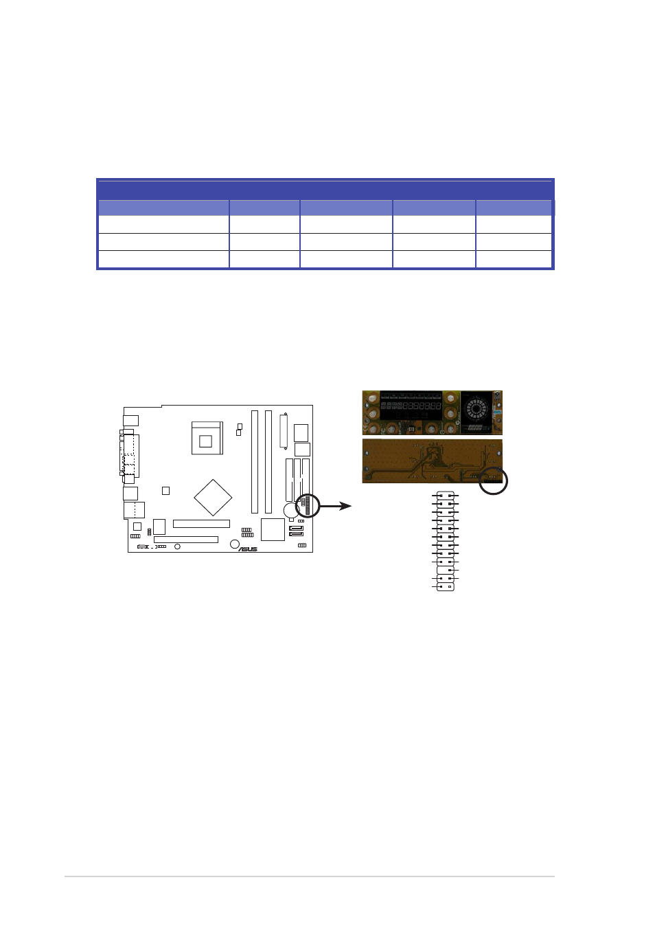
P4P8T LCD_PANEL connector
LCD_PANEL
PIC_CLK
+5VSB
GND
PIC_STB#
PIC_DOUT
PIC_CLK
PIC_DIN
PIC_DIN
PIC_STB#
PIC_DOUT
DJ_PLAY
+5V
DJ_SCANFW
DJ_SCANRW
SMBDATA
+5VSB
SMBCLK
GND
+12V
DJ_VOLUP
DJ_VOLDN
DJ_STOP#
9 .
9 .
9 .
9 .
9 .
L C D p a n e l c o n n e c t o r ( 2 4 - 1 - p i n L C D _ P A N E L )
L C D p a n e l c o n n e c t o r ( 2 4 - 1 - p i n L C D _ P A N E L )
L C D p a n e l c o n n e c t o r ( 2 4 - 1 - p i n L C D _ P A N E L )
L C D p a n e l c o n n e c t o r ( 2 4 - 1 - p i n L C D _ P A N E L )
L C D p a n e l c o n n e c t o r ( 2 4 - 1 - p i n L C D _ P A N E L )
This connector is for the LCD panel on the front panel of the S1-P111
model.
Required IDE Configuration settings in BIOS
Refer to the following table for the appropriate BIOS settings of the
above P-ATA and S-ATA device configurations. See section “5.3. 5 IDE
Configuration” for details on the related BIOS items.
W i n d o w s
W i n d o w s
W i n d o w s
W i n d o w s
W i n d o w s
®
®
®
®
®
W i n d o w s
W i n d o w s
W i n d o w s
W i n d o w s
W i n d o w s
®
®
®
®
®
9 8 / M E / N T 4 . 0
9 8 / M E / N T 4 . 0
9 8 / M E / N T 4 . 0
9 8 / M E / N T 4 . 0
9 8 / M E / N T 4 . 0
B I O S i t e m
B I O S i t e m
B I O S i t e m
B I O S i t e m
B I O S i t e m
2 0 0 0 / X P
2 0 0 0 / X P
2 0 0 0 / X P
2 0 0 0 / X P
2 0 0 0 / X P
A
A
A
A
A
B
B
B
B
B
C
C
C
C
C
Onboard IDE Operate Mode
Enhanced Mode
Compatible Mode
Compatible Mode
Compatible Mode
Enhanced Mode Support On
S-ATA
—
—
—
IDE Port Settings
—
Primary P-ATA+S-ATA Sec. P-ATA+S-ATA
P-ATA Ports Only