Ac`97 – Asus M2A-MX User Manual
Page 45
ASUS M2A-MX
1-33
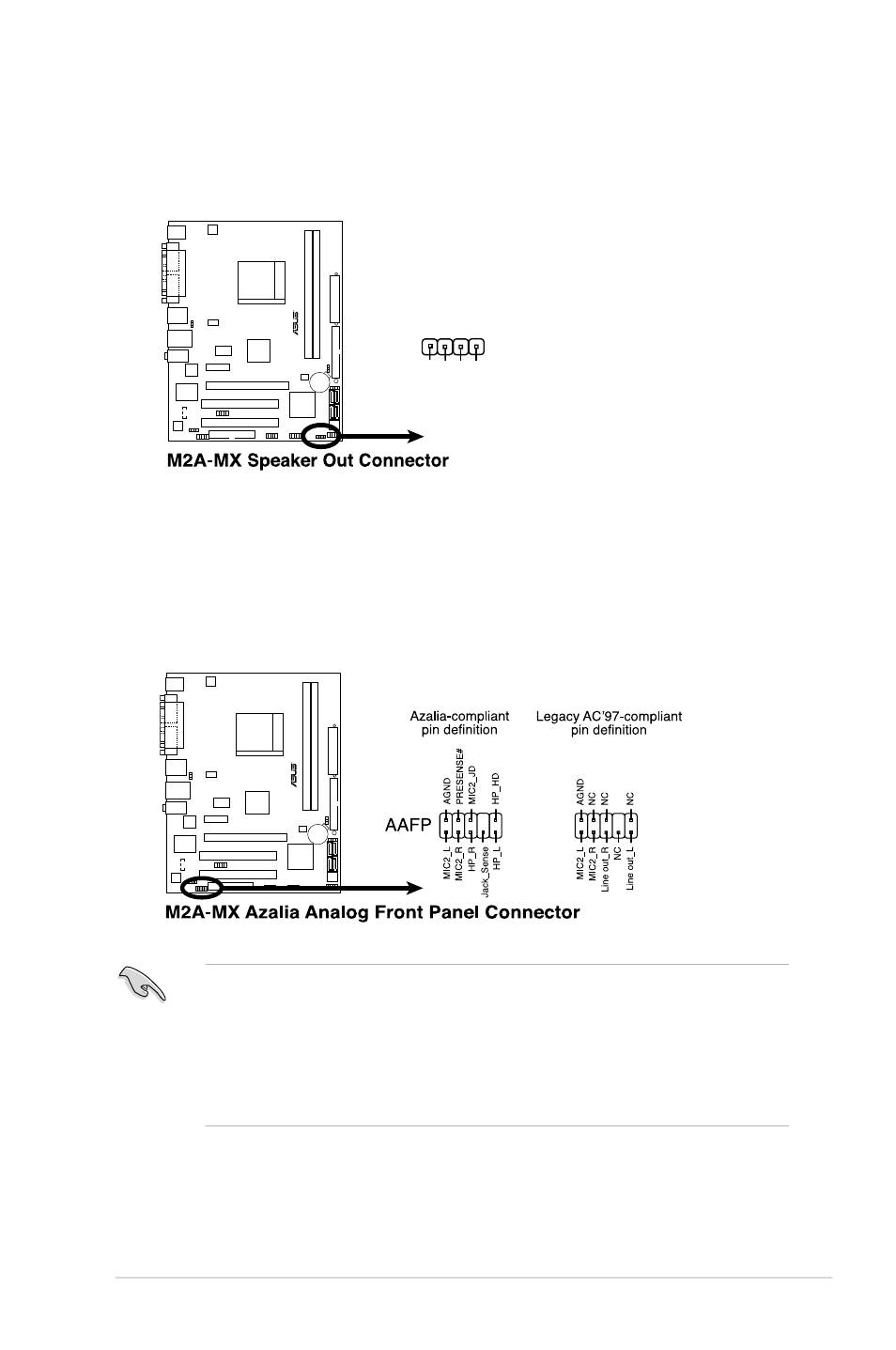
10. Front panel audio connector (10-1 pin AAFP)
This connector is for a chassis-mounted front panel audio I/O module that
supports either High Definition Audio or AC`97 audio standard. Connect one
end of the front panel audio I/O module cable to this connector.
• We recommend that you connect a high-definition front panel audio module
to this connector to avail of the motherboard high-definition audio capability.
• If you want to connect a high-definition front panel audio module to this
connector, make sure that the Front Panel Select item in the BIOS is set
to [HD Audio]; if you want to connect an
AC`97
front panel audio module to
this connector, set the item to [AC97]. See page 2-25 for details.
9. Speaker connector (4-pin SPEAKER)
This connector is for the chassis-mounted system warning speaker. The
speaker allows you to hear system beeps and warnings.
M2A-MX
R
SPEAKER
+5
V
GN
D
GN
D
Speaker Ou
t
1
M2A-MX
R
- Nuvifone G60 (100 pages)
- MyPal A632N (104 pages)
- A696 (109 pages)
- P565 (190 pages)
- PadFone (8 pages)
- PadFone (10 pages)
- PadFone (106 pages)
- PadFone (4 pages)
- MyPal A639 (106 pages)
- MyPal A639 (104 pages)
- WAVI (197 pages)
- MyPal A600 (110 pages)
- MyPal A632 (6 pages)
- MYPAL 632 (142 pages)
- MyPal A632 (104 pages)
- MyPal A620BT (156 pages)
- PadFone Infinity (74 pages)
- PadFone Infinity (12 pages)
- PadFone Infinity (14 pages)
- PadFone Infinity (4 pages)
- PadFone Infinity (8 pages)
- The new PadFone Infinity (69 pages)
- MyPal A716 (6 pages)
- MyPal A716 (166 pages)
- R600 (10 pages)
- R300 (4 pages)
- R600 (109 pages)
- MeMO Pad FHD 10 LTE (98 pages)
- MyPal A730W (218 pages)
- MyPal A730W (6 pages)
- MeMO Pad FHD 10 (96 pages)
- MyPal A730 (6 pages)
- MyPal A730 (204 pages)
- R300 (17 pages)
- R300 (89 pages)
- P5WDG2 WS Professional (172 pages)
- P5WDG2 WS Professional (691 pages)
- P5WDG2 WS Professional (170 pages)
- P5VDC-X (92 pages)
- P7P55D-E Premium (134 pages)
- M2N-PLUS SLI Vista Edition (154 pages)
- H81M-A/BR (48 pages)
- P8H67-I (58 pages)
- P8P67 PRO (REV 3.1) (136 pages)
- H61M-F (74 pages)