Asus T2-PH1 User Manual
Page 68
4 - 1 0
4 - 1 0
4 - 1 0
4 - 1 0
4 - 1 0
C h a p t e r 4 : M o t h e r b o a r d i n f o
C h a p t e r 4 : M o t h e r b o a r d i n f o
C h a p t e r 4 : M o t h e r b o a r d i n f o
C h a p t e r 4 : M o t h e r b o a r d i n f o
C h a p t e r 4 : M o t h e r b o a r d i n f o
1 0 .
1 0 .
1 0 .
1 0 .
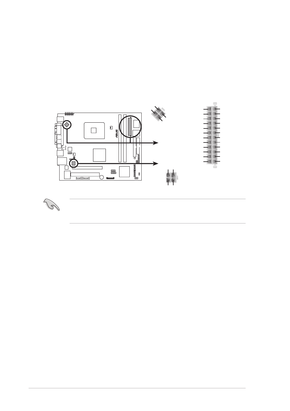
1 0 . ATX power connectors (24-pin ATXPWR, 4-pin ATX12V1,
A T X p o w e r c o n n e c t o r s ( 2 4 - p i n A T X P W R , 4 - p i n A T X 1 2 V 1 ,
A T X p o w e r c o n n e c t o r s ( 2 4 - p i n A T X P W R , 4 - p i n A T X 1 2 V 1 ,
A T X p o w e r c o n n e c t o r s ( 2 4 - p i n A T X P W R , 4 - p i n A T X 1 2 V 1 ,
A T X p o w e r c o n n e c t o r s ( 2 4 - p i n A T X P W R , 4 - p i n A T X 1 2 V 1 ,
4 - p i n A T X 1 2 V 2 )
4 - p i n A T X 1 2 V 2 )
4 - p i n A T X 1 2 V 2 )
4 - p i n A T X 1 2 V 2 )
4 - p i n A T X 1 2 V 2 )
These connectors are for the 24-pin and 4-pin power plugs from the
power supply unit. The plugs from the power supply unit are designed
to fit these connectors in only one orientation. Find the proper
orientation and push down firmly until the connectors completely fit.
®
ATX power connectors
ATX12V1
ATXPWR
+12V DC
GND
+12V DC
GND
+3 Volts
+3 Volts
Ground
+5 Volts
+5 Volts
Ground
Ground
Power OK
+5V Standby
+12 Volts
-5 Volts
+5 Volts
+3 Volts
-12 Volts
Ground
Ground
Ground
PSON#
Ground
+5 Volts
+12 Volts
+3 Volts
+5 Volts
1
Ground
+12V DC
Ground
+12V DC
Ground
ATX12V2
Do not forget to connect the two 4-pin ATX12V power plugs to the
ATX12V1 and ATX12V2 connectors on the motherboard; otherwise, the
system will not boot up.