5 internal components – Asus T2-P User Manual
Page 21
21
ASUS Terminator 2 barebone system
See page 60 for the wireless LAN adapter LED indications.
25. AIR LED. This green LED blinks when the wireless LAN adapter is
transmitting or receiving data.
1.5
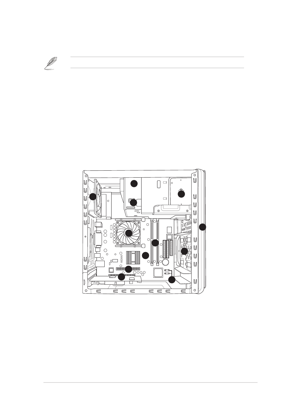
Internal components
The illustration below is the internal view of the system when you remove the
top cover and the power supply unit (see page 37 for details). The installed
components are labeled for your reference. Proceed to Chapter 2 for
instructions on installing other system components.
1. Optical drive
2. 5.25-inch empty optical drive bay
3. Floppy disk drive
4. Front panel cover
5. Hard disk drive metal tray
6. Chassis fan
7. ASUS P4P8T motherboard
8. DIMM sockets
9. CPU fan and heatsink assembly
10. AGP slot
11. PCI slot (with an installed
PCI card)
12. SATA connectors
3
9
10
6
5
4
11
7
8
1
2
12
26. Gigabit LAN port. (for Deluxe models-Commercial edition only) This
port allows high speed connection to the Internet via a DSL or cable
modem.
- CG8565 (410 pages)
- CG8565 (246 pages)
- CS5111 (26 pages)
- CS5120 (1 page)
- ET1611PUK (38 pages)
- S2-P8H61E (80 pages)
- P2-PH1 (80 pages)
- P1-P5945G (80 pages)
- P2-P5945GCX (90 pages)
- CG8270 (72 pages)
- CG8270 (76 pages)
- CG8270 (534 pages)
- CG8270 (362 pages)
- CG8270 (218 pages)
- CG8270 (536 pages)
- P3-P5G31 (100 pages)
- P3-PH4 (80 pages)
- P2-M2A690G (80 pages)
- P2-M2A690G (8 pages)
- P4-P5N9300 (82 pages)
- P4-P5N9300 (1 page)
- P1-P5945GC (92 pages)
- P2-P5945GC (92 pages)
- P3-P5G33 (98 pages)
- T3-P5945GCX (80 pages)
- T3-P5945GC (80 pages)
- P2-M2A690G (94 pages)
- T3-PH1 (80 pages)
- T3-PH1 (82 pages)
- T5-P5G41E (76 pages)
- T5-P5G41E (82 pages)
- S1-AT5NM10E (68 pages)
- P6-P7H55E (67 pages)
- ES5000 (174 pages)
- T4-P5G43 (104 pages)
- T-P5G31 (92 pages)
- BT6130 (2 pages)
- BT6130 (60 pages)
- BT6130 (54 pages)
- CG8265 (350 pages)
- CG8265 (210 pages)
- CM1740 (198 pages)
- CM1740 (330 pages)
- CM1740 (70 pages)
- P6-M4A3000E (59 pages)