9 asus v-series p5g33 – Asus V3-P5G33 User Manual
Page 65
4-9
ASUS V-Series P5G33
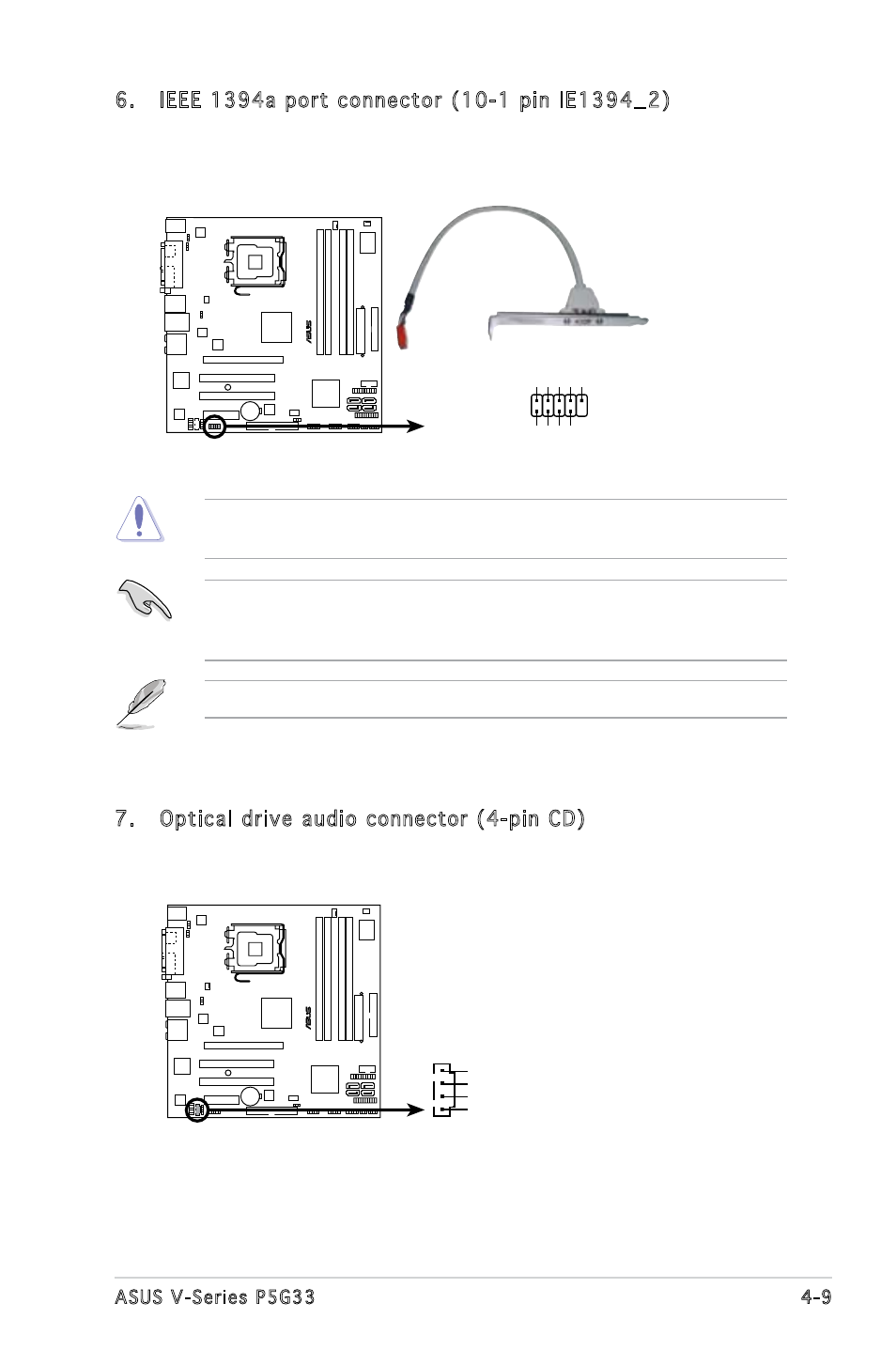
6. IEEE 1394a port connector (10-1 pin IE1394_2)
This connector is for a IEEE 1394a port. Connect the IEEE 1394a
module cable to this connector, then install the module to a slot
opening at the back of the system chassis.
P5K-VM
®
P5K-VM IEEE 1394a connector
IE1394_2
PIN 1
GND
+12V
TPB2-
GND
TP
A2-
+12V
TPB2+
GND
TP
A2+
Never connect a USB cable to the IEEE 1394a connector. Doing so will
damage the motherboard!
You can connect the front panel 1394 cable to the ASUS Q-Connector
(1394, red) first, and then install the Q-Connector (1394) to the 1394
connector onboard if your chassis supports front panel 1394 ports.
The IEEE 1394a module cable is purchased separately.
7. Optical drive audio connector (4-pin CD)
These connectors allow you to receive stereo audio input from sound
sources such as a CD-ROM, TV tuner, or MPEG card.
P5K-VM
®
P5K-VM Internal audio connector
CD
Right Audio Channel
Left Audio Channel
Ground
Ground
- CG8565 (410 pages)
- CG8565 (246 pages)
- CS5120 (1 page)
- CS5111 (26 pages)
- ET1611PUK (38 pages)
- S2-P8H61E (80 pages)
- P2-P5945GCX (90 pages)
- P2-PH1 (80 pages)
- P1-P5945G (80 pages)
- CG8270 (534 pages)
- CG8270 (362 pages)
- CG8270 (218 pages)
- CG8270 (536 pages)
- CG8270 (72 pages)
- CG8270 (76 pages)
- P3-P5G31 (100 pages)
- P3-PH4 (80 pages)
- P2-M2A690G (8 pages)
- P2-M2A690G (80 pages)
- P4-P5N9300 (82 pages)
- P4-P5N9300 (1 page)
- P2-P5945GC (92 pages)
- P1-P5945GC (92 pages)
- P3-P5G33 (98 pages)
- T3-P5945GC (80 pages)
- T3-P5945GCX (80 pages)
- P2-M2A690G (94 pages)
- T3-PH1 (82 pages)
- T3-PH1 (80 pages)
- T5-P5G41E (76 pages)
- T5-P5G41E (82 pages)
- S1-AT5NM10E (68 pages)
- P6-P7H55E (67 pages)
- ES5000 (174 pages)
- T4-P5G43 (104 pages)
- T-P5G31 (92 pages)
- BT6130 (60 pages)
- BT6130 (54 pages)
- BT6130 (2 pages)
- CG8265 (350 pages)
- CG8265 (210 pages)
- CM1740 (330 pages)
- CM1740 (70 pages)
- CM1740 (198 pages)
- P6-M4A3000E (59 pages)