Asus P5N32-SLI Deluxe User Manual
Page 166
6 - 4
6 - 4
6 - 4
6 - 4
6 - 4
C h a p t e r 6 : N V I D I A
C h a p t e r 6 : N V I D I A
C h a p t e r 6 : N V I D I A
C h a p t e r 6 : N V I D I A
C h a p t e r 6 : N V I D I A
®
®
®
®
®
S L I ™ t e c h n o l o g y s u p p o r t
S L I ™ t e c h n o l o g y s u p p o r t
S L I ™ t e c h n o l o g y s u p p o r t
S L I ™ t e c h n o l o g y s u p p o r t
S L I ™ t e c h n o l o g y s u p p o r t
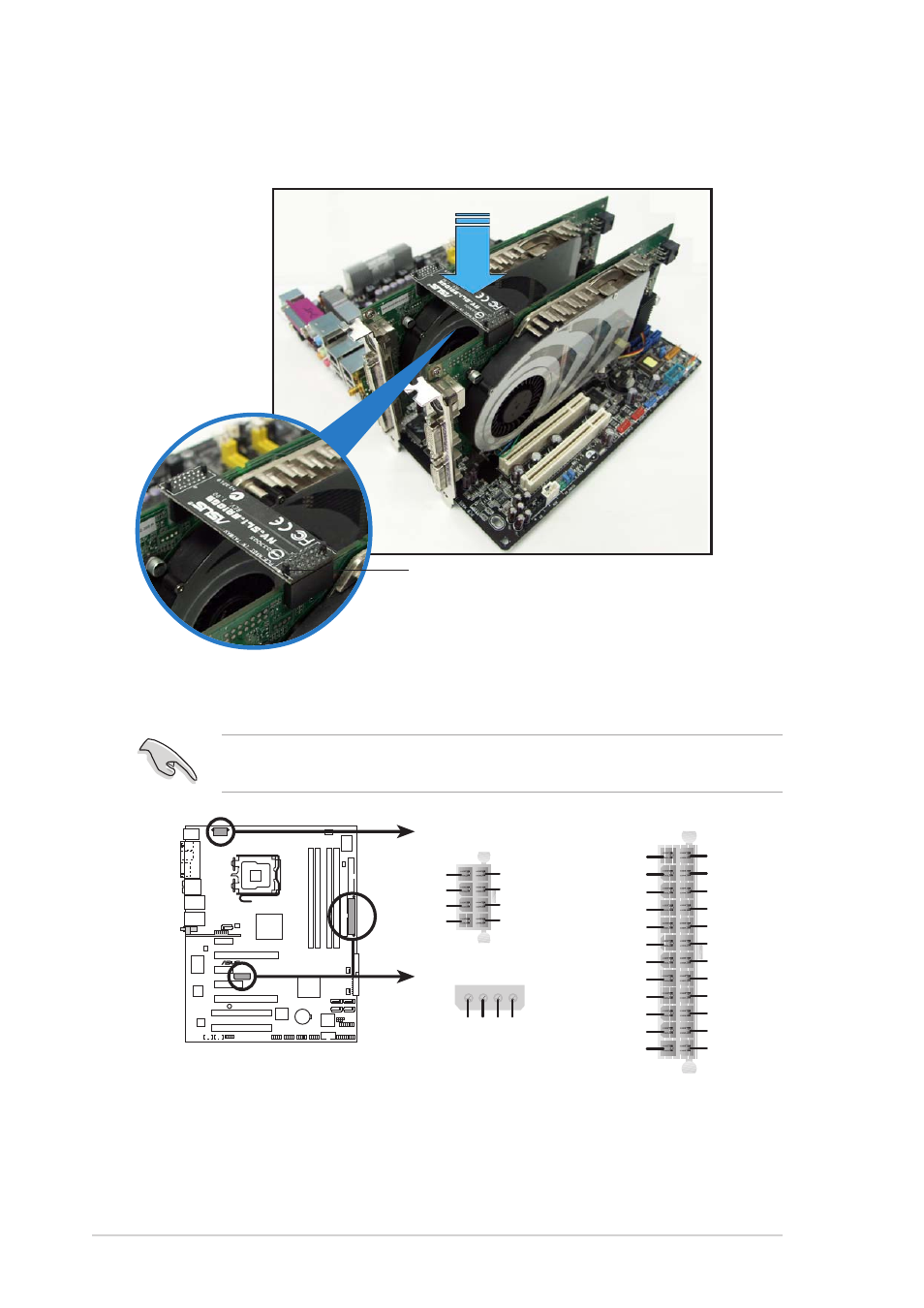
5.
Align and insert the SLI connector to the goldfingers on each graphics
card. Make sure that the connector is firmly in place.
6.
Connect a 4-pin ATX power cable to the EZ Plug™ labeled E Z _ P L U G
E Z _ P L U G
E Z _ P L U G
E Z _ P L U G
E Z _ P L U G
on your motherboard.
S L I c o n n e c t o r
S L I c o n n e c t o r
S L I c o n n e c t o r
S L I c o n n e c t o r
S L I c o n n e c t o r
Make sure to connect a 4-pin ATX power cable to the EZ Plug; otherwise,
the system will be unstable.
P5N32-SLI
®
P5N32-SLI ATX power connectors
EATXPWR
ATX12V
EZ_PLUG
+5V
EZ_DET
GND
+12V
+3 Volts
+3 Volts
Ground
+5 Volts
+5 Volts
Ground
Ground
Power OK
+5V Standby
+12 Volts
-5 Volts
+5 Volts
+3 Volts
-12 Volts
Ground
Ground
Ground
PSON#
Ground
+5 Volts
+12 Volts
+3 Volts
+5 Volts
Ground
GND
+12V DC
GND
+12V DC
GND
+12V DC
GND
+12V DC