Iii. installation, Asus p2e-m motherboard layout, 12 asus p2e-m user’s manual – Asus P2E-M User Manual
Page 12: Motherboard layout iii. inst alla tion, Intel 440ex agpset, Single edge contact cpu slot (slot 1)
12
ASUS P2E-M User’s Manual
III. INSTALLATION
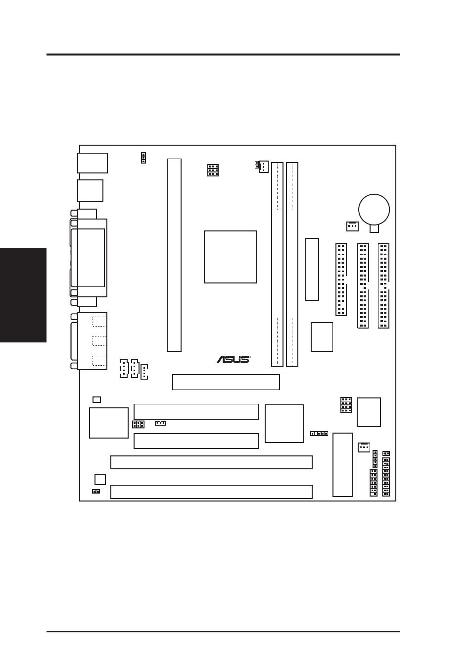
ASUS P2E-M Motherboard Layout
Motherboard Layout
III. INST
ALLA
TION
R
Top: USB 1
Bottom: USB 2
PS/2
USB
Top: Mouse
Bottom: Keyboard
COM1
COM2
GAME/AUDIO
Mic
In
Line
Out
Line
In
Single Edge Contact CPU Slot (Slot 1)
Row
DIMM Socket 1 (64-bit, 168-pin module)
3 2
Intel
440EX
AGPset
PWR_FAN
CPU_FAN
DIMM Socket 2 (64-bit, 168-pin module)
1 0
Intel
PIIX4
PCIset
CR2032 3V
Lithium Cell
BIOS Power
Secondary IDE
Primary IDE
Floppy Drives
CHA_FAN
Accelerated Graphics Port
PCI Slot 1
PCI Slot 2
ISA Slot 1
ISA Slot 2
A
TX Power Connector
Panel Connectors
IR
VP
ANEL
Frequency Ratio
SMB
ASUS
AS97127F
Multi-i/O
Chip
Audio
Chipset
CD2
CD1
AUX
BUS Frequency
RT3
P
ARALLEL
POR
T
Wake on LAN
SPDIFO
KBPWR
IDELED
RT2
1Mbit Flash EEPROM
(Programmable BIOS)
Hardware Monitor
NOTE: Audio chipset and connectors available with onboard audio model only.
- P5B (140 pages)
- P5B (56 pages)
- P5B Premium Vista Edition (188 pages)
- P5KPL-VM/1394/SI (94 pages)
- M2N68-CM (28 pages)
- P5GD1-VM (88 pages)
- P5AD2 Premium (8 pages)
- P5GD1-VM (92 pages)
- P5AD2-E Premium (2 pages)
- DELUXE A7N8X-E (114 pages)
- P5KPL-AM SE (40 pages)
- P5KPL-AM SE (38 pages)
- P5KPL-AM SE (62 pages)
- P4S8X-X (64 pages)
- P5K-VM (98 pages)
- K8V-X SE (82 pages)
- M2N68-AM SE2 (40 pages)
- P4P800 SE (125 pages)
- P4P800 SE (16 pages)
- DELUXE SERIES M3A32-MVP (176 pages)
- P5AD2 Deluxe (148 pages)
- M4A79 Deluxe (122 pages)
- A7V266-E (108 pages)
- Application Manual (2 pages)
- Application Manual (6 pages)
- Application Manual (9 pages)
- Application Manual (3 pages)
- Application Manual (1 page)
- Application Manual (5 pages)
- Application Manual (11 pages)
- Application Manual (10 pages)
- Application Manual (4 pages)
- Application Manual (8 pages)
- M4A88T-I DELUXE (70 pages)
- M4A88T-I DELUXE (44 pages)
- RAMPAGE IV GENE (1 page)
- P9X79 (156 pages)
- P9X79 DELUXE (2 pages)
- P8H61-M PLUS V3 (64 pages)
- A85XM-A (78 pages)
- M4A78L-M LE (64 pages)
- M2N68-AM (38 pages)
- M2N68-AM (96 pages)
- M2N68-AM (62 pages)
- Blitz Extreme (188 pages)