Chapter 2 – Asus P8P67 PRO User Manual
Page 40
2-22
Chapter 2: Hardware information
Chapter 2
4.
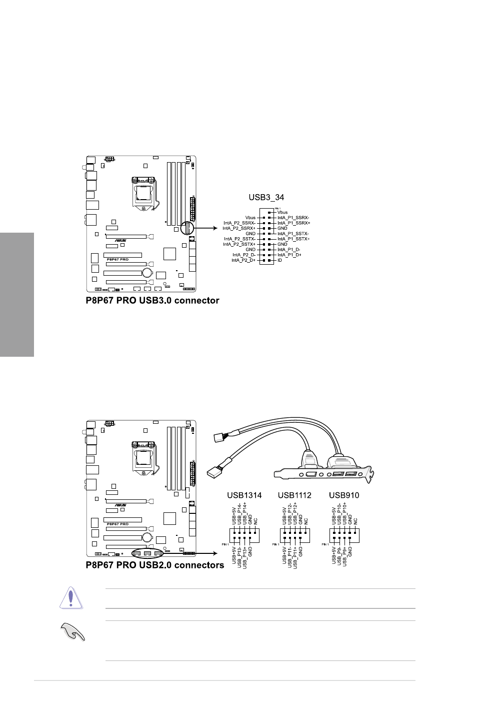
USB 3.0 connector (20-1 pin USB3_34)
This connector is for the additional USB 3.0 ports. Connect the bundled USB 3.0
bracket cable to this connector, then install the USB 3.0 bracket to the rear side of the
chassis. If your chassis support customised front panel installation, with ASUS USB 3.0
header, you can have a front panel USB 3.0 solution.
You can connect the front panel USB cable to the ASUS Q-Connector (USB, blue) first, and
then install the Q-Connector (USB) to the USB connector onboard if your chassis supports
front panel USB ports.
Never connect a 1394 cable to the USB connectors. Doing so will damage the motherboard!
5.
USB 2.0 connectors (10-1 pin USB910; USB1112; USB1314)
These connectors are for USB 2.0 ports. Connect the USB module cable to any of
these connectors, then install the module to a slot opening at the back of the system
chassis. These USB connectors comply with USB 2.0 specification that supports up to
48 Mbps connection speed.
- P5B (56 pages)
- P5B Premium Vista Edition (188 pages)
- P5B (140 pages)
- P5KPL-VM/1394/SI (94 pages)
- M2N68-CM (28 pages)
- P5AD2 Premium (8 pages)
- P5GD1-VM (92 pages)
- P5AD2-E Premium (2 pages)
- P5GD1-VM (88 pages)
- DELUXE A7N8X-E (114 pages)
- P5KPL-AM SE (40 pages)
- P5KPL-AM SE (38 pages)
- P5KPL-AM SE (62 pages)
- P4S8X-X (64 pages)
- P5K-VM (98 pages)
- K8V-X SE (82 pages)
- M2N68-AM SE2 (40 pages)
- P4P800 SE (125 pages)
- P4P800 SE (16 pages)
- DELUXE SERIES M3A32-MVP (176 pages)
- P5AD2 Deluxe (148 pages)
- M4A79 Deluxe (122 pages)
- A7V266-E (108 pages)
- Application Manual (9 pages)
- Application Manual (3 pages)
- Application Manual (1 page)
- Application Manual (5 pages)
- Application Manual (11 pages)
- Application Manual (10 pages)
- Application Manual (4 pages)
- Application Manual (8 pages)
- Application Manual (2 pages)
- Application Manual (6 pages)
- M4A88T-I DELUXE (70 pages)
- M4A88T-I DELUXE (44 pages)
- P9X79 (156 pages)
- P9X79 DELUXE (2 pages)
- RAMPAGE IV GENE (1 page)
- P8H61-M PLUS V3 (64 pages)
- A85XM-A (78 pages)
- M4A78L-M LE (64 pages)
- M2N68-AM (38 pages)
- M2N68-AM (96 pages)
- M2N68-AM (62 pages)
- Blitz Extreme (188 pages)