Usb3_56 – Asus F1A75-M PRO User Manual
Page 36
8.
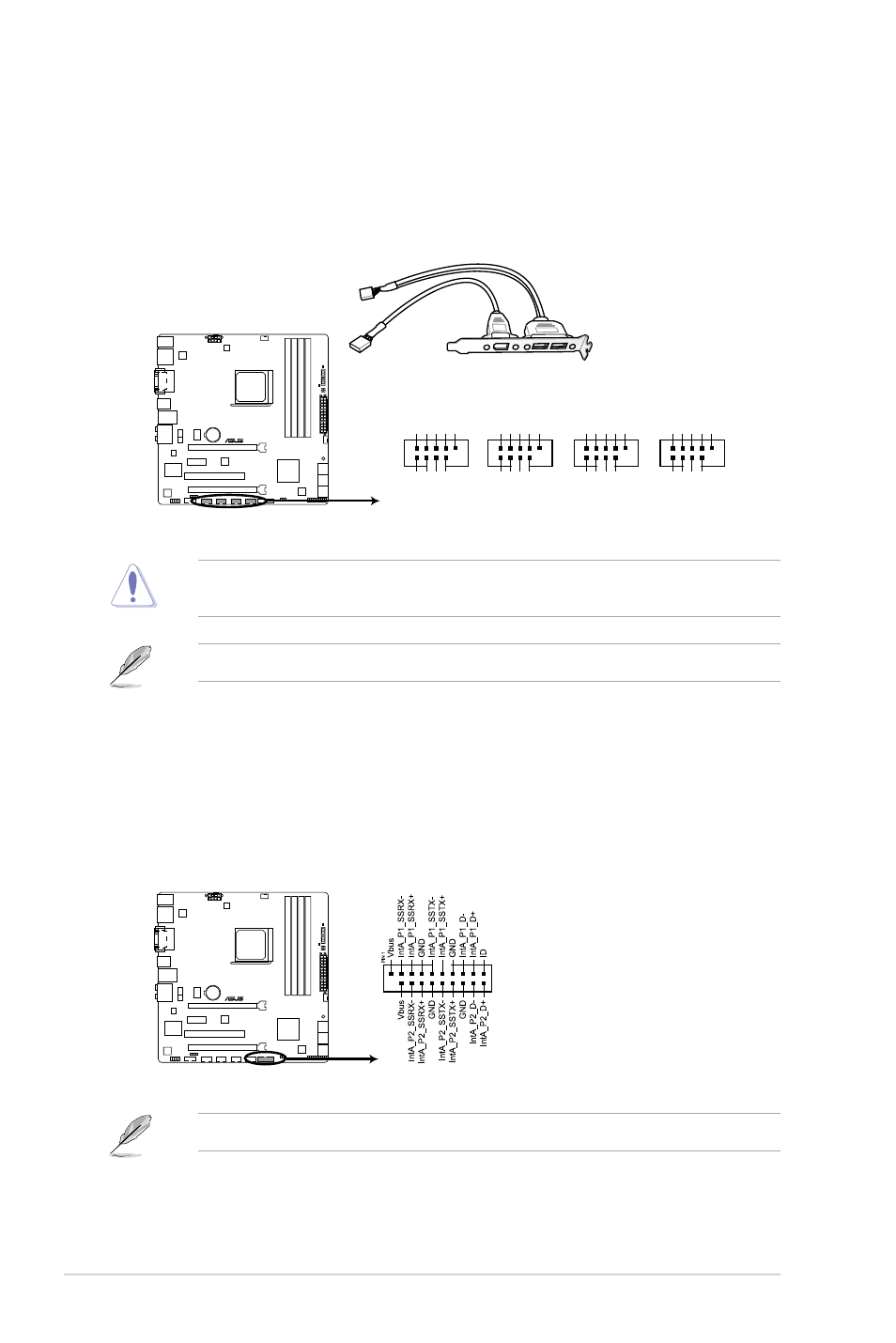
USB 2.0 connectors (10-1 pin USB34, USB56, USB78, USB910)
These connectors are for USB 2.0 ports. Connect the USB module cable to any of
these connectors, then install the module to a slot opening at the back of the system
chassis. These USB connectors comply with USB 2.0 specification that supports up to
480Mbps connection speed.
Never connect a 1394 cable to the USB connectors. Doing so will damage the
motherboard!
The USB 2.0 module is purchased separately.
F1A75-M PRO
F1A75-M PRO USB2.0 connectors
USB+5V
USB_P4-
USB_P4+
GND
NC
USB+5V
USB_P5-
USB_P5+
GND
USB34
PIN 1
USB+5V
USB_P6-
USB_P6+
GND
NC
USB+5V
USB_P5-
USB_P5+
GND
USB56
PIN 1
USB+5V
USB_P10-
USB_P10+
GND
NC
USB+5V
USB_P9-
USB_P9+
GND
USB910
PIN 1
USB+5V
USB_P8-
USB_P8+
GND
NC
USB+5V
USB_P7-
USB_P7+
GND
USB78
PIN 1
9.
USB 3.0 connector (20-1 pin USB3_34)
This connector is for the additional USB 3.0 ports. Connect the USB 3.0 bracket cable
to this connector, then install the USB 3.0 bracket to the rear side of the chassis. If your
chassis support customized front panel installation, with ASUS USB 3.0 header, you
can have a front panel USB 3.0 solution.
F1A75-M PRO
F1A75-M PRO USB3.0 Front panel connector
USB3_56
The USB 3.0 module is purchased separately.
Chapter 1: Product introduction
1-24