Asus NCL-DS1R1 User Manual
Page 53
A S U S N C L - D S 1 S e r i e s
A S U S N C L - D S 1 S e r i e s
A S U S N C L - D S 1 S e r i e s
A S U S N C L - D S 1 S e r i e s
A S U S N C L - D S 1 S e r i e s
2 - 3 3
2 - 3 3
2 - 3 3
2 - 3 3
2 - 3 3
9 .
9 .
9 .
9 .
9 .
B a c k p l a n e S M B u s c o n n e c t o r ( 6 - 1 p i n B P S M B 1 )
B a c k p l a n e S M B u s c o n n e c t o r ( 6 - 1 p i n B P S M B 1 )
B a c k p l a n e S M B u s c o n n e c t o r ( 6 - 1 p i n B P S M B 1 )
B a c k p l a n e S M B u s c o n n e c t o r ( 6 - 1 p i n B P S M B 1 )
B a c k p l a n e S M B u s c o n n e c t o r ( 6 - 1 p i n B P S M B 1 )
This connector allows you to connect SMBus (System Management
Bus) devices. Devices communicate with an SMBus host and/or other
SMBus devices using the SMBus interface.
1 0 .
1 0 .
1 0 .
1 0 .
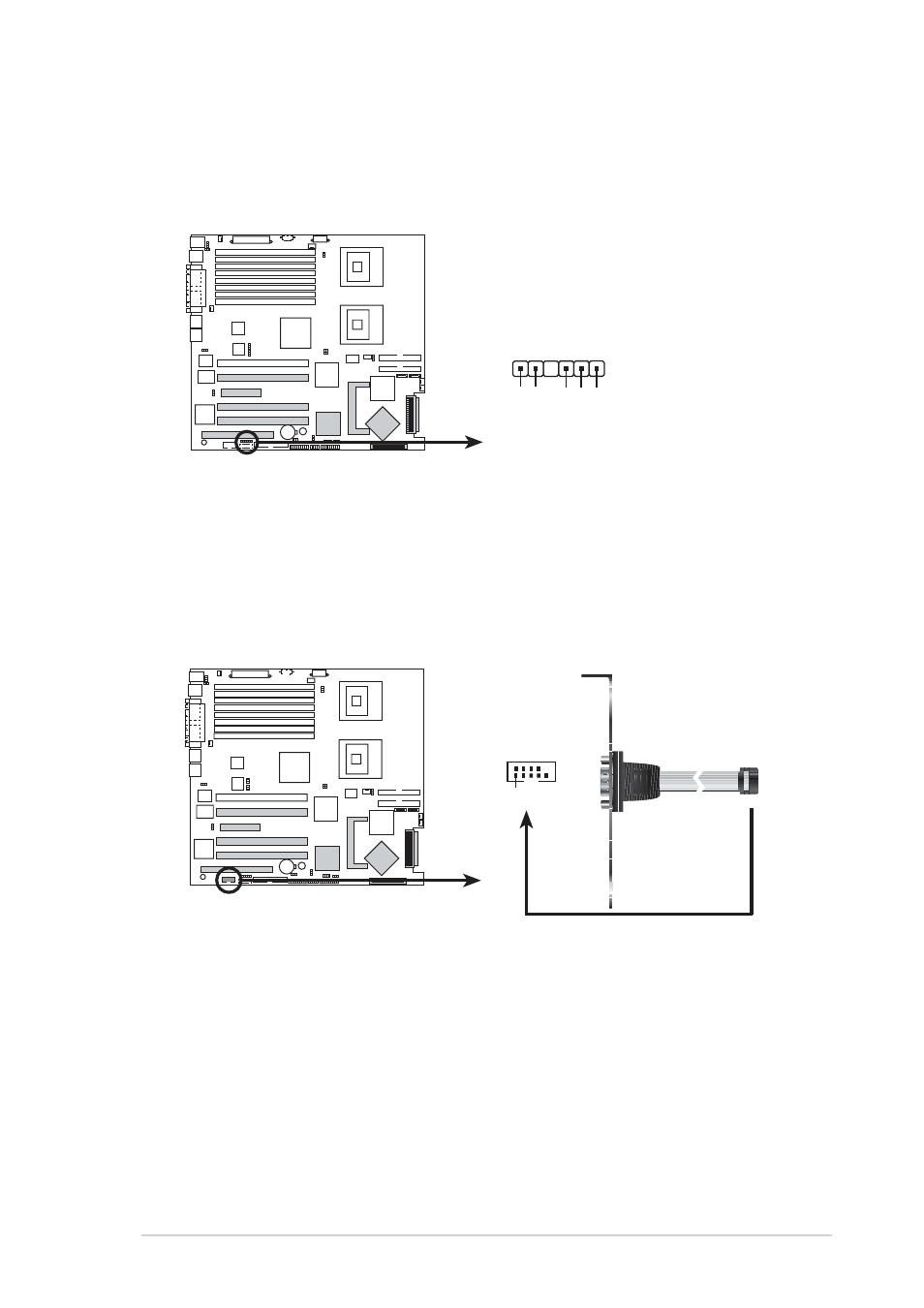
1 0 . Serial port connector (10-1 pin COM2)
S e r i a l p o r t c o n n e c t o r ( 1 0 - 1 p i n C O M 2 )
S e r i a l p o r t c o n n e c t o r ( 1 0 - 1 p i n C O M 2 )
S e r i a l p o r t c o n n e c t o r ( 1 0 - 1 p i n C O M 2 )
S e r i a l p o r t c o n n e c t o r ( 1 0 - 1 p i n C O M 2 )
This connector is for a serial (COM) port. Connect the serial port
module cable to this connector, then install the module to a slot
opening at the back of the system chassis.
NCL-DS1 Series SMBus connector
BPSMB1
1
I2C_6_CLK#
GND
I2C_6_DA
T
A
#
+5V
F
AN_DC
NCL-DS1 Series Serial port connectors
PIN 1
COM2