1 overview overview overview overview overview – Asus NCL-DS1R1 User Manual
Page 35
A S U S N C L - D S 1 S e r i e s
A S U S N C L - D S 1 S e r i e s
A S U S N C L - D S 1 S e r i e s
A S U S N C L - D S 1 S e r i e s
A S U S N C L - D S 1 S e r i e s
2 - 1 5
2 - 1 5
2 - 1 5
2 - 1 5
2 - 1 5
2.4
System memory
2.4.1
2.4.1
2.4.1
2.4.1
2.4.1
Overview
Overview
Overview
Overview
Overview
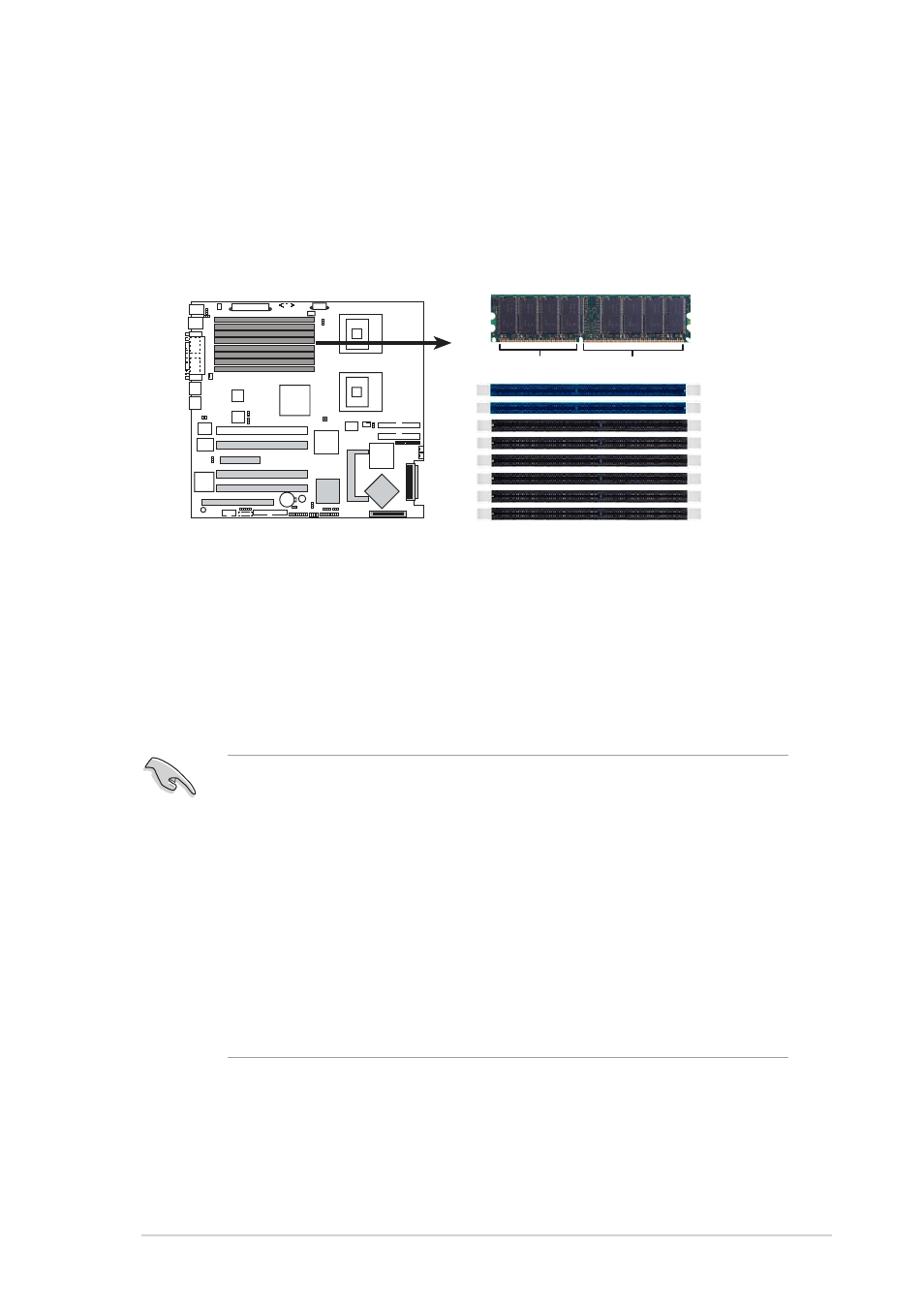
The motherboard comes with eight Double Data Rate (DDR) Dual Inline
Memory Modules (DIMM) sockets to support 184-pin DDR modules.
The figure illustrates the location of the DDR DIMM sockets:
2.4.2
2.4.2
2.4.2
2.4.2
2.4.2
Memory configurations
Memory configurations
Memory configurations
Memory configurations
Memory configurations
You may install 256 MB, 512 MB, 1 GB, and 2 GB registered ECC DDR
DIMMs into the DIMM sockets.
•
Always install DIMMs with the same CAS latency. For optimum
compatibility, it is recommended that you obtain memory modules
from the same vendor. Refer to the DDR Qualified Vendors List at
the ASUS web site.
•
Due to chipset resource allocation, the system may detect less than
16 GB system memory when you installed eight 2 GB DDR2 memory
modules.
•
This motherboard does not support memory modules made up of
128 Mb chips or double-rank x16 memory modules.
•
If you are installing only one memory module, install into the blue
socket labeled DIMM_B4. Installing into any other socket would not
work.
DIMM_A1
DIMM_B1
NCL-DS1 Series 184-pin DDR DIMM sockets
DIMM_A2
DIMM_B2
DIMM_A3
DIMM_B3
DIMM_A4
DIMM_B4
80 Pins
104 Pins