Asus P5GD1 User Manual
Page 47
A S U S P 5 G D 1
A S U S P 5 G D 1
A S U S P 5 G D 1
A S U S P 5 G D 1
A S U S P 5 G D 1
2 - 2 7
2 - 2 7
2 - 2 7
2 - 2 7
2 - 2 7
6 .
6 .
6 .
6 .
6 .
S e r i a l p o r t c o n n e c t o r ( 1 0 - 1 p i n C O M 2 )
S e r i a l p o r t c o n n e c t o r ( 1 0 - 1 p i n C O M 2 )
S e r i a l p o r t c o n n e c t o r ( 1 0 - 1 p i n C O M 2 )
S e r i a l p o r t c o n n e c t o r ( 1 0 - 1 p i n C O M 2 )
S e r i a l p o r t c o n n e c t o r ( 1 0 - 1 p i n C O M 2 )
This connector is for a serial (COM) port. Connect the serial port
module cable to this connector, then install the module to a slot
opening at the back of the system chassis.
Never connect a 1 3 9 4 c a b l e
1 3 9 4 c a b l e
1 3 9 4 c a b l e
1 3 9 4 c a b l e
1 3 9 4 c a b l e to the USB connectors. Doing so will
damage the motherboard!
7 .
7 .
7 .
7 .
7 .
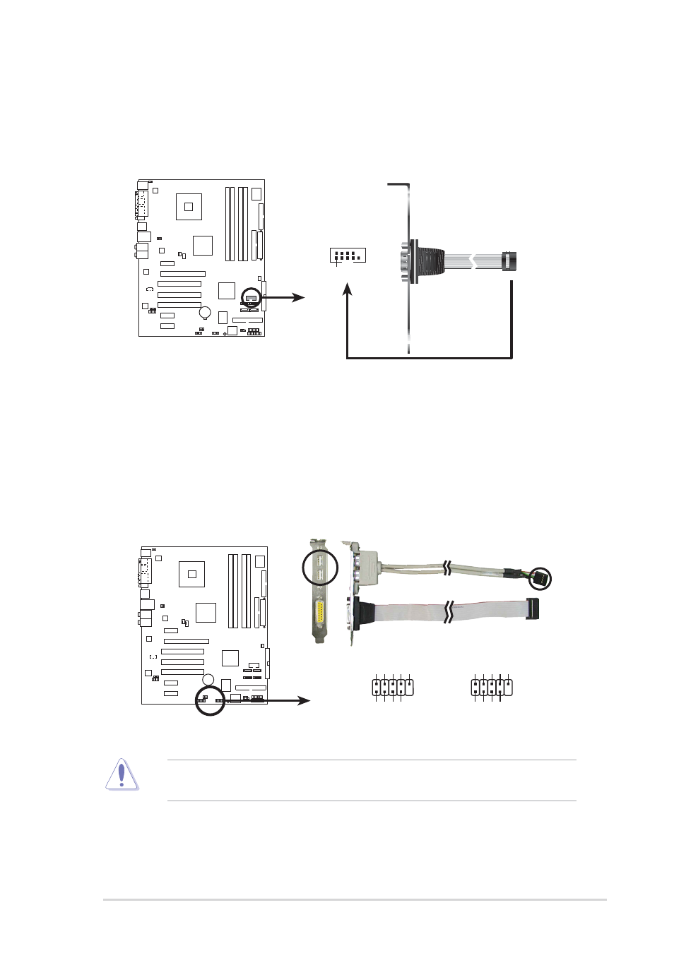
U S B c o n n e c t o r s ( 1 0 - 1 p i n U S B 5 6 , U S B 7 8 )
U S B c o n n e c t o r s ( 1 0 - 1 p i n U S B 5 6 , U S B 7 8 )
U S B c o n n e c t o r s ( 1 0 - 1 p i n U S B 5 6 , U S B 7 8 )
U S B c o n n e c t o r s ( 1 0 - 1 p i n U S B 5 6 , U S B 7 8 )
U S B c o n n e c t o r s ( 1 0 - 1 p i n U S B 5 6 , U S B 7 8 )
These connectors are for USB 2.0 ports. Connect the USB/GAME
module cable to any of these connectors, then install the module to a
slot opening at the back of the system chassis. These USB connectors
comply with USB 2.0 specification that supports up to 480 Mbps
connection speed.
P5GD1
P5GD1 Serial port connectors
PIN 1
COM2
P5GD1
P5GD1 USB 2.0 connectors
USB56
USB+5V
USB_P6-
USB_P6+
GND
NC
USB+5V
USB_P5-
USB_P5+
GND
1
USB78
USB+5V
USB_P8-
USB_P8+
GND
NC
USB+5V
USB_P7-
USB_P7+
GND
1