Hardware setup, 1 cusi-m motherboard layout, Socket 370 – Asus CUSI-M User Manual
Page 14: Sis630e 3c integration single chip, Pci slot 1 pci slot 2, Pci slot 3, 14 asus cusi-m user’s manual, Motherboard layout 3. h/w setup, Primary ide secondary ide
14
ASUS CUSI-M User’s Manual
3. HARDWARE SETUP
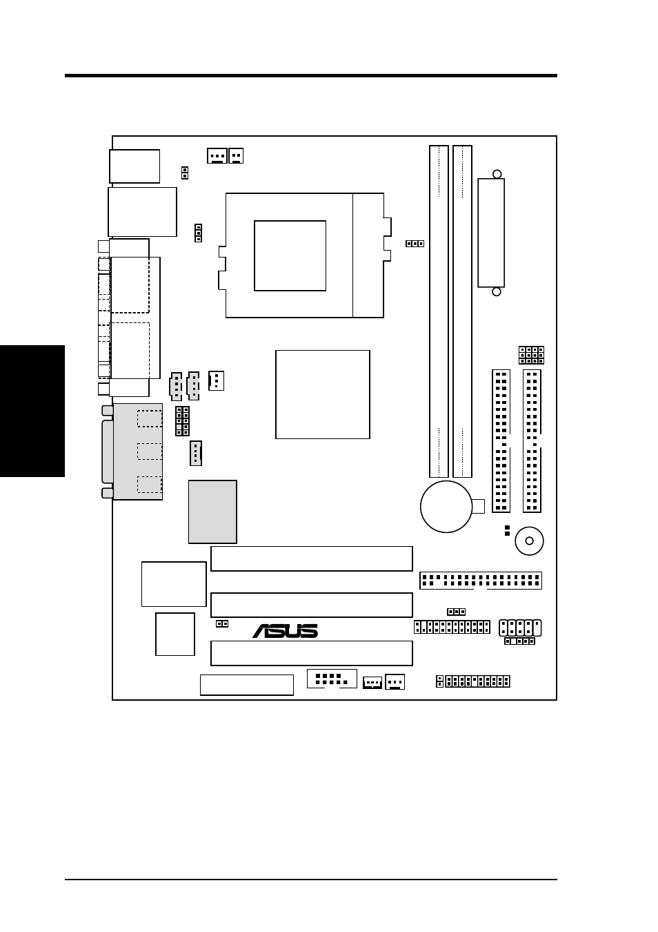
3.1 CUSI-M Motherboard Layout
Motherboard Layout
3. H/W SETUP
FLOPPY
CPU_FAN
PANEL
WOL_CON
Row
ATXPWR
BUZZER
CR2032 3V
Lithium Cell
CMOS Power
CD1
PWR_FAN
SiS630E
3C
Integration
Single
Chip
COM1
P
ARALLEL
POR
T
VGA
PS/2
T: Mouse
B: Keyboard
GAME_AUDIO
Mic
In
Line
Out
Line
In
Bottom:
USB1
USB2
Top:
RJ-45
AUX
USBPWR1
PWRTMP
SCPU
IDELED
USB1
USB2
CH_FAN
USBPWR0
CUSI-M
®
CLRTC
AFPANEL
WOR
AUDIO_PANEL
JEN
MODEM
JP3 JP1 JP2 JP0
Socket 370
32-bit
PCI
Audio
Chipset
ITE 8705
Super I/O
2Mbit
Flash
BIOS
Audio Modem Riser
(AMR)
PCI Slot 1
PCI Slot 2
DIMM Socket 1 (64/72-bit, 168-pin module)
1
0
01
DIMM Socket 2 (64/72-bit, 168-pin module)
3
2
A
TX Power Connector
Primary IDE
Secondary IDE
PCI Slot 3
COM2
NOTE: Gray components are optional at the time of purchase.
See also other documents in the category Asus Motherboard:
- P5B Premium Vista Edition (188 pages)
- P5B (140 pages)
- P5B (56 pages)
- P5KPL-VM/1394/SI (94 pages)
- M2N68-CM (28 pages)
- P5GD1-VM (92 pages)
- P5AD2-E Premium (2 pages)
- P5GD1-VM (88 pages)
- P5AD2 Premium (8 pages)
- DELUXE A7N8X-E (114 pages)
- P5KPL-AM SE (62 pages)
- P5KPL-AM SE (40 pages)
- P5KPL-AM SE (38 pages)
- P4S8X-X (64 pages)
- P5K-VM (98 pages)
- K8V-X SE (82 pages)
- M2N68-AM SE2 (40 pages)
- P4P800 SE (16 pages)
- P4P800 SE (125 pages)
- DELUXE SERIES M3A32-MVP (176 pages)
- P5AD2 Deluxe (148 pages)
- M4A79 Deluxe (122 pages)
- A7V266-E (108 pages)
- Application Manual (4 pages)
- Application Manual (8 pages)
- Application Manual (2 pages)
- Application Manual (6 pages)
- Application Manual (9 pages)
- Application Manual (3 pages)
- Application Manual (1 page)
- Application Manual (5 pages)
- Application Manual (11 pages)
- Application Manual (10 pages)
- M4A88T-I DELUXE (44 pages)
- M4A88T-I DELUXE (70 pages)
- P9X79 DELUXE (2 pages)
- RAMPAGE IV GENE (1 page)
- P9X79 (156 pages)
- P8H61-M PLUS V3 (64 pages)
- A85XM-A (78 pages)
- M4A78L-M LE (64 pages)
- M2N68-AM (96 pages)
- M2N68-AM (62 pages)
- M2N68-AM (38 pages)
- Blitz Formula (2 pages)