8 connecting cables, Front panel buttons and leds – Asus V2-AE1 User Manual
Page 35
2 - 1 9
2 - 1 9
2 - 1 9
2 - 1 9
2 - 1 9
A S U S V i n t a g e 2 - A E 1
A S U S V i n t a g e 2 - A E 1
A S U S V i n t a g e 2 - A E 1
A S U S V i n t a g e 2 - A E 1
A S U S V i n t a g e 2 - A E 1
2.8
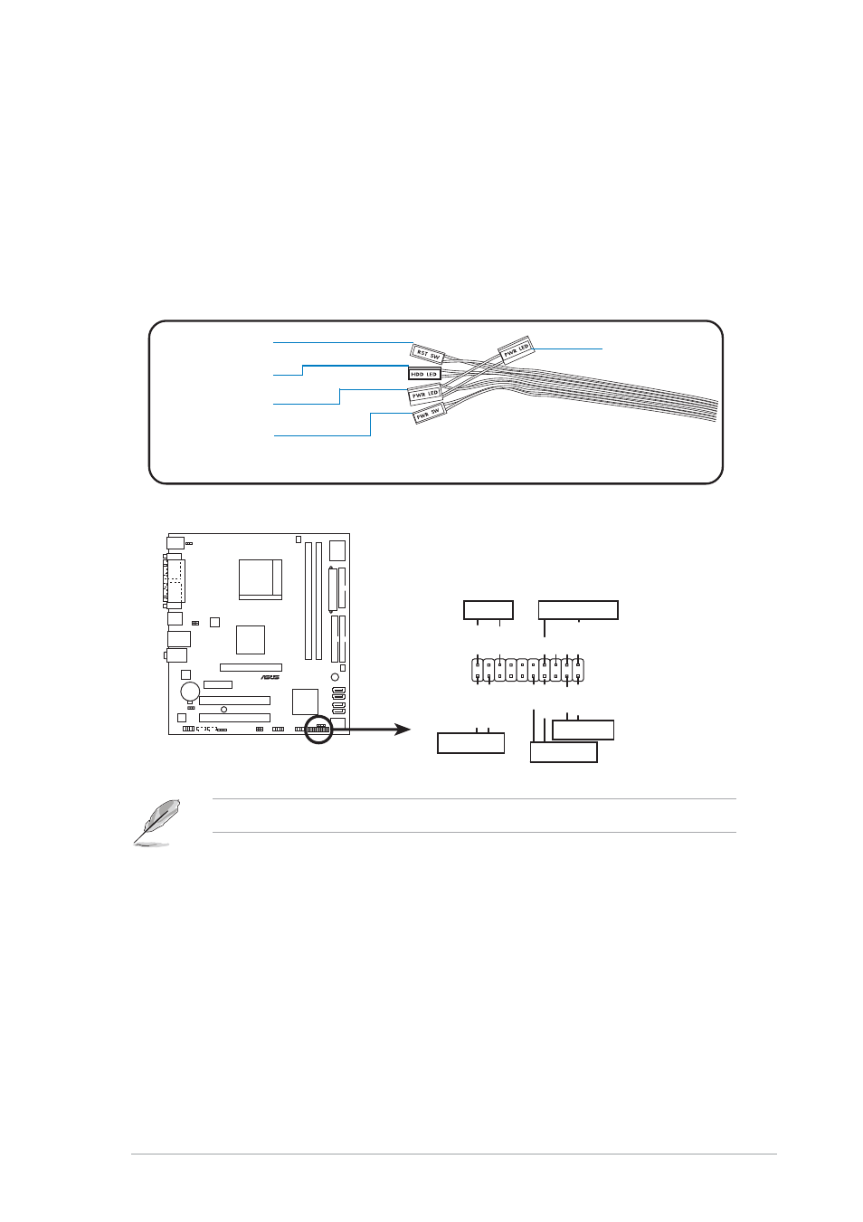
Connecting cables
You may have disconnected some cables when you installed system
components. Connect these cables before you replace the chassis cover.
Front panel buttons and LEDs
Front panel buttons and LEDs
Front panel buttons and LEDs
Front panel buttons and LEDs
Front panel buttons and LEDs
Connect the r e s e t b u t t o n , p o w e r s w i t c h
r e s e t b u t t o n , p o w e r s w i t c h
r e s e t b u t t o n , p o w e r s w i t c h
r e s e t b u t t o n , p o w e r s w i t c h
r e s e t b u t t o n , p o w e r s w i t c h, p o w e r L E D ,
p o w e r L E D ,
p o w e r L E D ,
p o w e r L E D ,
p o w e r L E D , and H D D
H D D
H D D
H D D
H D D
L E D
L E D
L E D
L E D
L E D cables to their respective leads in the system panel connector on the
motherboard. See page 4-12 for the system panel descriptions.
H D D L E D
H D D L E D
H D D L E D
H D D L E D
H D D L E D
P o w e r L E D
P o w e r L E D
P o w e r L E D
P o w e r L E D
P o w e r L E D
P o w e r S w i t c h
P o w e r S w i t c h
P o w e r S w i t c h
P o w e r S w i t c h
P o w e r S w i t c h
R e s e t b u t t o n
R e s e t b u t t o n
R e s e t b u t t o n
R e s e t b u t t o n
R e s e t b u t t o n
P o w e r L E D *
P o w e r L E D *
P o w e r L E D *
P o w e r L E D *
P o w e r L E D *
®
System panel connector
*
Requires an ATX power supply.
PLED-
PWR
+5V
Speaker
PLED
Ground
RESET
Ground
Reset
Ground
Ground
PLED+
IDE_LED-
IDE_LED+
IDE_LED
SPEAKER
PWRSW
PANEL
*The extra 2-pin power LED is for other Vintage2 models.