Français, Ab b – Asus P5L-VM 1394 User Manual
Page 2
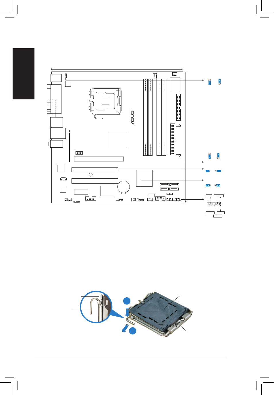
ASUS P5L-VM 1394
Français
1.
Schéma de la Carte Mère
2.
Installation du Processeur
Suivez cette procédure pour installer un processeur Intel
®
dans le
paquet 775-land.
1. Appuyez sur le levier de chargement avec votre pouce (A), puis
déplacez-le vers le gauche (B) jusqu’à ce qu’il soit détaché de la
languette de retenue.
Languette de
retenue
Levier de
chargement
Ce côté du boîtier cam
doit être face à vous.
Capuchon PnP
A
B
B
24.5cm (9.6in)
24.5cm (9.6in
)
LGA775
CPU_FAN
DDR2 DIMM_A1 (64 bit,240-pin module)
DDR2 DIMM_A2 (64 bit,240-pin module)
DDR2 DIMM_B1 (64 bit,240-pin module)
DDR2 DIMM_B2 (64 bit,240-pin module)
CHA_FAN1
Super I/O
FL
O
PP
Y
PR
I_
EI
DE
EA
TXPW
R
SATA3
SATA4
SATA1
SATA2
COM1
PANEL
CHASSIS
CLRTC
USB56
USB78
USBPW56
SPI_J1
4MB
BIOS
IE1394_2
CR2032 3V
Lithium Cell
CMOS Power
Intel GMCH945G
Intel ICH7
SPDIF_OUT
CD
AAFP
PCI2
PCI1
PCIEX16
PCIEX1_1
SB_PWR
VIA
VT6308P
Attansic L1
P5L-VM 19
USBPW12
KBPWR
PS/2KBMS
T: Mouse
B: Keyboard
PA
RA
LL
E
P
OR
T
VGA
LAN_USB34
F_USB12
AUDIO
ATX12V
VG
A
R
*
Requires an ATX power supply
NEL
PLED-
PWR
+5V
Speaker
Ground
RESET
Ground
Reset
Ground Ground
PWRSW
PLED+
IDE_LED-
IDE_LED+
IDE_LED
PLED
SPEAKER
PA
CLRTC
Normal
Clear CMOS
(Default)
1 2
2 3
(Default)
+5V
+5VSB
KBPWR
2
3
1
2
3
2
2
1
USBPW12
+5V
(Default)
+5VSB
USBPW56
3
2
2
1
+5V
(Default)
+5VSB
ALC883