Asus AP1600R-E2(AI2) User Manual
Page 63
A S U S A P 1 6 0 0 R - E 2 ( A A 2 / A I 2 )
A S U S A P 1 6 0 0 R - E 2 ( A A 2 / A I 2 )
A S U S A P 1 6 0 0 R - E 2 ( A A 2 / A I 2 )
A S U S A P 1 6 0 0 R - E 2 ( A A 2 / A I 2 )
A S U S A P 1 6 0 0 R - E 2 ( A A 2 / A I 2 )
4 - 1 3
4 - 1 3
4 - 1 3
4 - 1 3
4 - 1 3
6 .
6 .
6 .
6 .
6 .
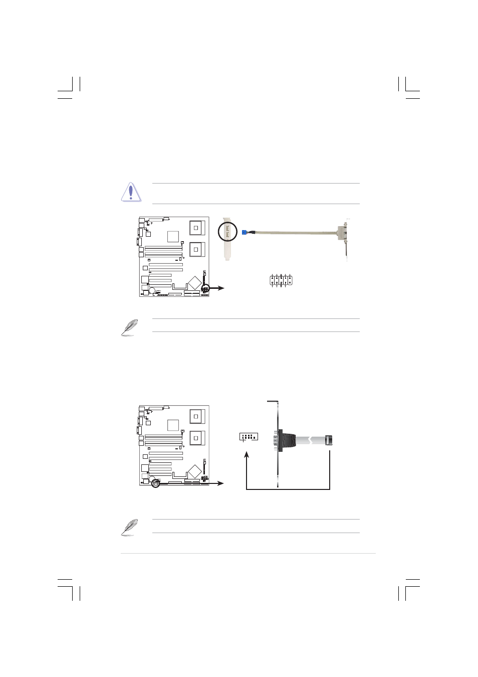
U S B p o r t c o n n e c t o r ( 1 0 - 1 p i n U S B 3 4 )
U S B p o r t c o n n e c t o r ( 1 0 - 1 p i n U S B 3 4 )
U S B p o r t c o n n e c t o r ( 1 0 - 1 p i n U S B 3 4 )
U S B p o r t c o n n e c t o r ( 1 0 - 1 p i n U S B 3 4 )
U S B p o r t c o n n e c t o r ( 1 0 - 1 p i n U S B 3 4 )
This connector is for additional USB 2.0 ports. Connect the USB
module cable to this connector, then install the module to a slot
opening at the back of the system chassis.
Never connect a 1 3 9 4 c a b l e
1 3 9 4 c a b l e
1 3 9 4 c a b l e
1 3 9 4 c a b l e
1 3 9 4 c a b l e to the USB connectors. Doing so will
damage the motherboard!
The USB port module is purchased separately.
NCCH-DR
USB+5V
USB_P4-
USB_P4+
GND
NC
NCCH-DR USB 2.0 connector
USB34
USB+5V
USB_P3-
USB_P3+
GND
7 .
7 .
7 .
7 .
7 .
S e r i a l p o r t c o n n e c t o r ( 1 0 - 1 p i n C O M 2 )
S e r i a l p o r t c o n n e c t o r ( 1 0 - 1 p i n C O M 2 )
S e r i a l p o r t c o n n e c t o r ( 1 0 - 1 p i n C O M 2 )
S e r i a l p o r t c o n n e c t o r ( 1 0 - 1 p i n C O M 2 )
S e r i a l p o r t c o n n e c t o r ( 1 0 - 1 p i n C O M 2 )
This connector is for a serial (COM) port. Connect the serial port
module cable to this connector, then install the module to a slot
opening at the back of the system chassis.
The serial port module is purchased separately.
NCCH-DR
NCCH-DR
Serial port2 (COM2) connector
PIN 1
COM2