The technical stuff, Terminal strip connections – Universal Audio 1176LN Solid-State User Manual
Page 24
The Technical Stuff
_____________________________________________________________
24
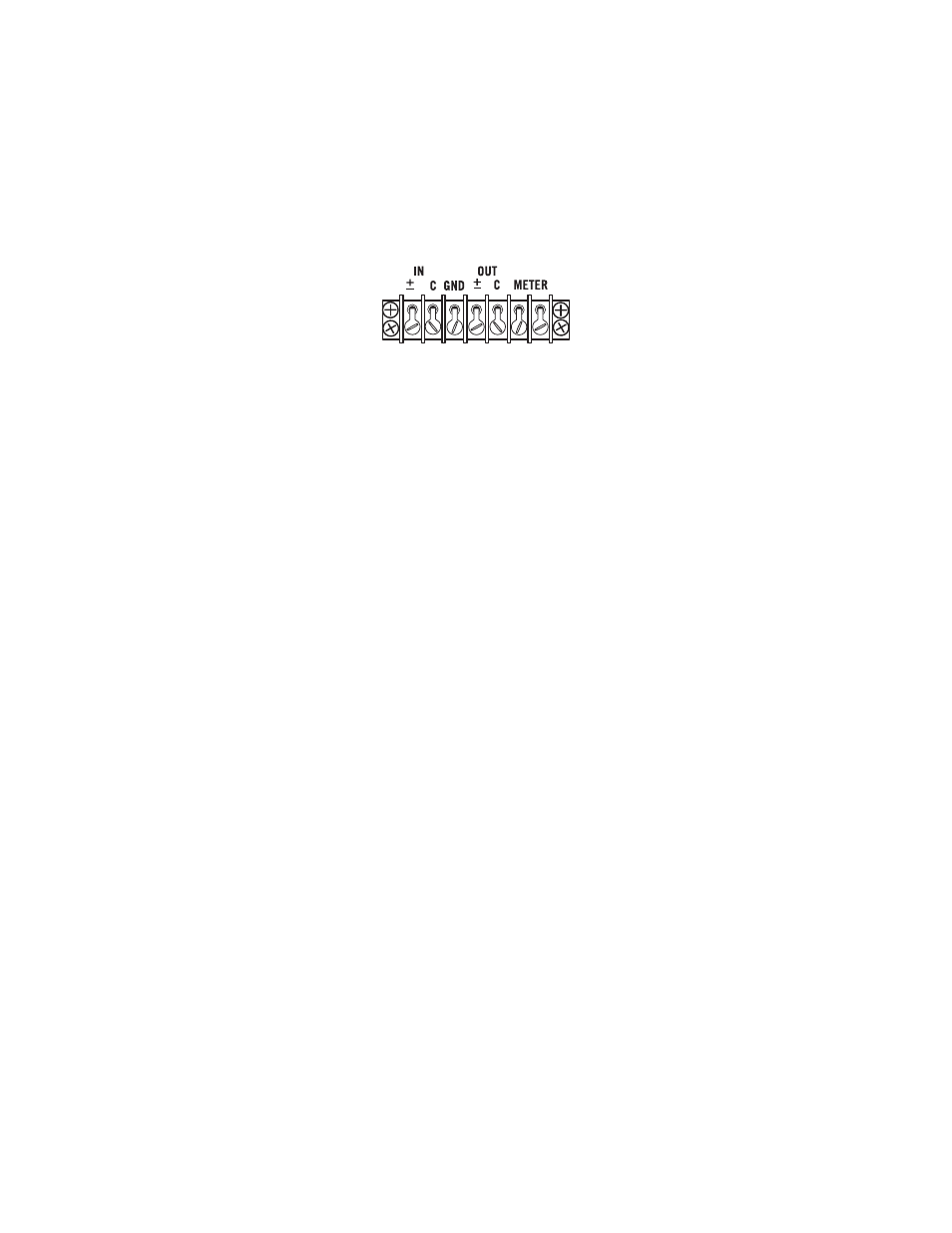
Terminal Strip Connections
Because it predated standard XLR connectors, the original 1176LN provided terminal strips for input
and output line-level connections, and so that feature has been retained here (in addition to providing
a modern XLR input and output).
The terminal strip inputs and outputs, from left to right, are as follows:
IN +/-
IN C (Common)
GND (Chassis Ground)
OUT +/-
OUT C (Common)
METER (two terminals, polarized; the inner terminal connects to meter plus and the outer
terminal to meter minus)
Only one input connection (XLR or terminal strip) to the 1176LN should be made, or induced noise may
result. However, so long as they are connected to devices of equal or greater impedance (i.e., most
modern audio equipment), both output connections can be used for simultaneous use of the terminal
strip and XLR output jacks.
Input and output connections should be made as follows:
UNBALANCED INPUT:
Connect the HOT cable lead (TS tip) to the IN +/- terminal
Connect the GROUND (shield braid) to the IN C terminal
UNBALANCED OUTPUT:
Connect the HOT cable lead (TS tip) to the OUT +/- terminal
Connect the GROUND (shield braid) to the OUT C terminal
BALANCED INPUT:
Connect the HOT cable lead (TRS tip or XLR pin 2) to the IN +/- terminal
Connect the NEUTRAL cable lead (TRS ring or XLR pin 3) to the IN C terminal
Optional: If there is a hum problem, connect the GROUND (shield braid or XLR pin 1)
to the GND terminal
BALANCED OUTPUT:
Connect the HOT cable lead (TRS tip or XLR pin 2) to the OUT +/- terminal
Connect the NEUTRAL cable lead (TRS ring or XLR pin 3) to the OUT C terminal
Connect the GROUND (shield braid or XLR pin 1) to the GND terminal
(NOTE: If hum results, the ground may be left disconnected)
The METER terminals provide a series insert point into the 1176LN’s meter side-chain circuitry,
allowing the connection of an external VU meter when desired. To do so, remove the shorting clip, and
then make a connection between the inner METER terminal (the one closest to OUT C) and the meter’s
positive input, and a second connection between the outer terminal (the one closest to the edge of the
terminal strip) and the meter’s negative input.