8 amp configuration 9 operating modes, 10 auxiliary port 11 input routing – Crown Audio ComTech DriveCore Series User Manual
Page 7
Operation Manual
CT Power Amplifiers
page 12
page 13
CT Power Amplifiers
Operation Manual
8 Amp Configuration
9 Operating Modes
8.1 70Hz HPF (High Pass Filter)
On the back panel, one 2-position high-pass filter
switch will only allow signals above 70Hz to be
amplified. This is to prevent transformer saturation.
The HPF, when turned on, is activated for all channels.
The filter is a 2nd order 12 dB/occ t filter.
8.2 Limiter
The limiter reduces amplifier gain to allow over drive
without harsh clipping at output.
When Amp Configuration Switch #5 is set to on
(pushed up), the amplifier will utilize the limiter feature.
DriveCore Amplifiers can work in a variety of
power modes.
9.1 Normal
The amplifier automaticaly operates full output power.
9.2 Green Power
Green mode utilizes Crown’s adaptive rail technology
for higher efficiency or power on demand. When Amp
Configuration DIP switch #4 is set to on, the amplifier
will operate in green mode.
For low input signal levels (less than –40dBu) the
amplifier will operate with minimum power.
The amplifier will increase to full power if either of the
following occurs:
1 - The input signal goes above -40dBu
2 - There is a single clip event from any of the channels
Likewise, if the amplifier is operating with full power,
the amplifier will decrease the operating rails to
minimum power if the input signal drops
below -40dBu.
Through the use of Green Power, the efficiency of the
amplifier dramatically increases for lower audio signal
reproduction. The adaptive rail technology used in the
CT amplifiers can increase the efficiency of the
amplifier by up to 10% with low signal levels.
9.3 Deep Sleep
See Section 10.1
Y
E
S
NO
NO
Y
E
S
Full Power
Minimum Power
Is green mode
DIP switch on?
Lower voltage rails
Increase rails to Full Power
Is there a clip
event?
Figure 9.2.1 How Green Power DIP switches work
10.1 Deep Sleep
In deep sleep mode, the amp consumes less than 1
watt of power. It is activated via the AUX port with a
ground closure.
To bring the amplifier out of deep sleep, remove the
ground closure via the AUX port.
10.2 Amp Status
The Amplifier Status is designed to work with life
safety or supervisory monitoring and control systems,
where notification of an amplifier fault is necessary.
The Amplifier Status is producing a signal
(Heartbeat or tone) when the amplifier is operating
within standard working parameters. If the amplifier
enters a fault or thermal condition, the Amplifier
Status signal will terminate. This feature in the
ComTech amplifier is always on. The Amplifier
Status is located on the Auxiliary Port, opposite the
deeP SLeeP function. The configuration of the Amp
Status signal is possible through DIP Switch #3:
• ON – the microcontroller will send a 1 Hz
pulse to the “AMP STATUS” AUX port line
• OFF – the microcontroller will send a logic
high level to the “AMP STATUS” AUX port line
The voltage output of the AuxPort is 5VDC at 50
milliamps. This TTL or similar signal can then be
connected to an interface to indicate the status to a
supervisory control system.
Amp status can be used in a variety of life safety
applications, such as EN54, IEC60849 among others.
10 Auxiliary Port
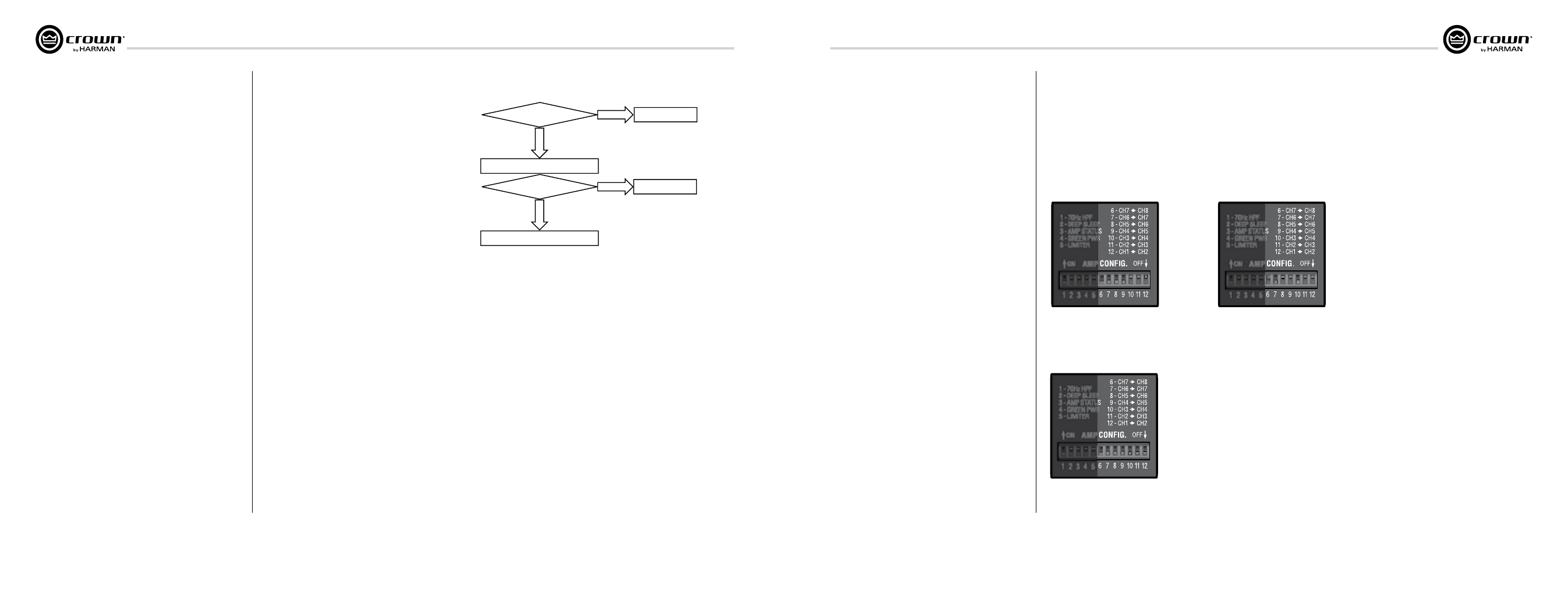
11 Input Routing
This amplifier can route a single channel to the next
numbered channel.
In CT 475 and CT 4150, DIP switches 6-9 are
non-functional.
When a DIP switch is set to “on” for a specific channel,
it sends the signal to its own output AND becomes the
input for the next numbered channel, overriding the
wired input for that channel.
Figure 11.1
Channel 1 intput sent to all channel
outputs, overriding channel inputs for
channels 2,3, and 4
Figure 11.2
Four input signals sent to four outputs
Figure 11.3
Channel 1 input sent to channels 1, 2, and 3
Channel 4 input sent to channels 4, 5, and 6
Channel 7 input sent to channels 7 and 8