4 setup – Crown Audio ComTech DriveCore Series User Manual
Page 4
Operation Manual
CT Power Amplifiers
page 6
page 7
CT Power Amplifiers
Operation Manual
4.1 Unpack Your Amplifier
Please unpack and inspect your amplifier for
any damage that may have occurred during
transit. If damage is found, notify the
transpor tation company immediately. Only you
can ini tiate a claim for shipping damage. Crown
will be happy to help as needed. Save the
shipping carton as evidence of damage for the
shipper’s inspection.
We also recommend that you save all packing
materials so you will have them if you ever need
to transport the unit. Never ship the unit
without the factory pack.
YOU WILL NEED (not supplied):
• Input wiring cables
• Output wiring cables
• Flathead screwdriver
Rack for mounting amplifier (or a stable surface
for stacking)
WARNiNg: Before you start to set up
your amplifier, make sure you read and
observe the important Safety instruc-
tions found at the beginning of this
manual.
4.2 Install Your Amplifier
cAUTiON: Before you begin, make sure
your amplifier is disconnected from the
power source and that all level controls
(see section 7.6) are set to 0.
The amplifier is 1.75” tall by 15.19” deep and
19” wide (see figure 4.2.1).
Mount the unit in a standard 19-inch (48.3-cm)
equipment rack (EIA RS-310B). You can also
place a single amp on a solid, stable surface or
stack multiple amps.
NOTE: When transporting, amplifiers should be
supported at both front and back.
4.3 Ensure Proper Cooling
When using an equipment rack, mount units
directly on top of each other. Close any open
spaces in the rack with blank panels. DO NOT
block front, top or side air vents.
The side walls of the rack should be a minimum
of two inches (5.1 cm) away from the amplifier
sides, and the back of the rack should be a
minimum of four inches (10.2 cm) from the
amplifier back panel. While the amplifier is
convection cooled and does not require a fan, it
is critical that the air vents are not covered.
Figure 4.2.1 CT Series Dimensions
4 Setup
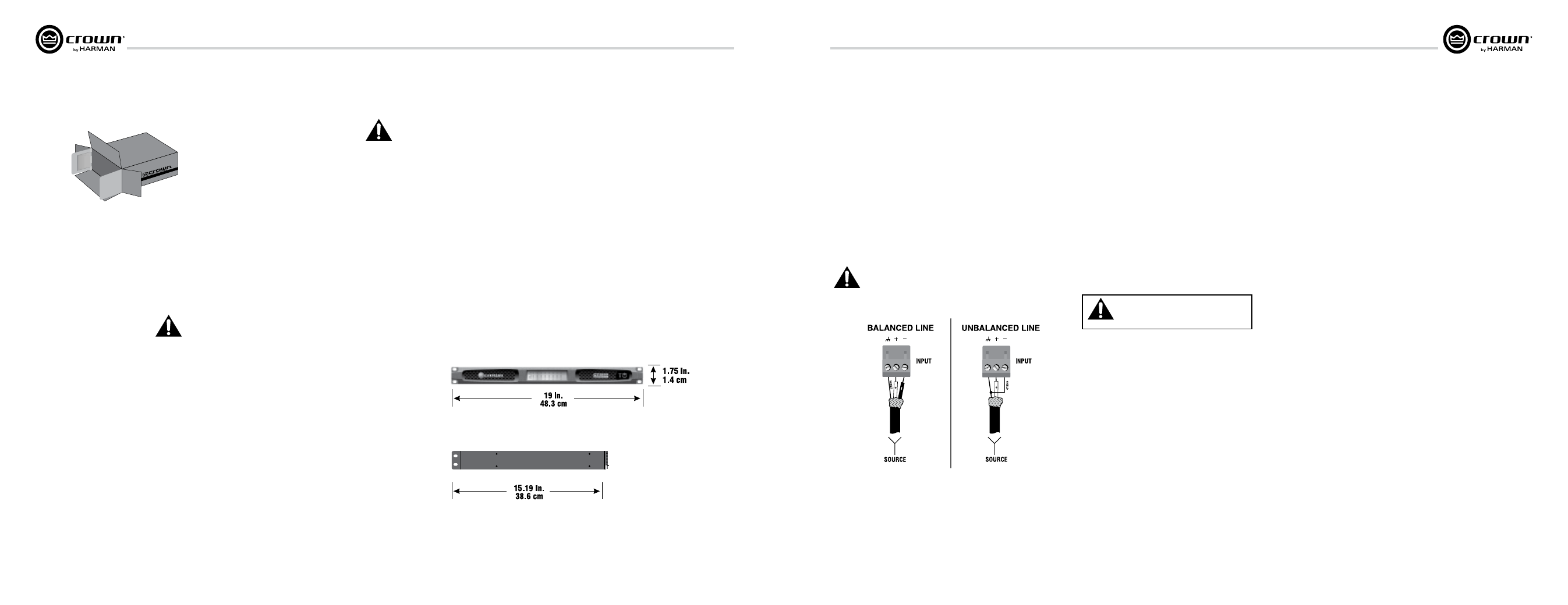
4.4 Choose Input Wire
and Connectors
Crown recommends using pre-built or
professionally wired balanced line (two-
conductor plus shield). Balanced wiring provides
better rejection of unwanted noise and hum but
unbalanced line may also be used. For more
information, refer to the Crown Amplifier
Application Guide, available online at www.
crownaudio.com.
Use 3-pin Phoenix-type cable ends at the amp
input connectors.
Figure 4.4.1 shows connector pin assignments
for balanced wiring and figure 4.4.2 shows
connector pin assignments for unbalanced wiring.
NOTe: custom wiring should only be
performed by qualified personnel. class 2
wiring is required.
4 Setup
Figure 4.4.1
Figure 4.4.2
4.5 Choose Output Wire and
Con nectors
Crown recommends using professionally
constructed, high quality, two-conductor, heavy
gauge speaker wire and connectors. Use 2-pin
Phoenix-type connectors (Included with the
amp).
Suggested below are guidelines to select the
appropriate size of wire based on the distance
from amplifier to speaker. Check with local code
as this may vary.
distance
Wire Size
up to 25 ft. (7.6m)
16 AWG
26-40 ft. (7.9-12.2m)
14 AWG
cAUTiON: Never use shielded cable for
output wiring.
cAUTiON: Never connect the speaker
return to the chassis of the amplifier, or
damage to the amplifier may result.
cAUTiON: Output of amplifier channels
cannot be bridged. This may damage the
amplifier.