Crown Audio JBL CSMA 180_1120 User Manual
Page 10
10
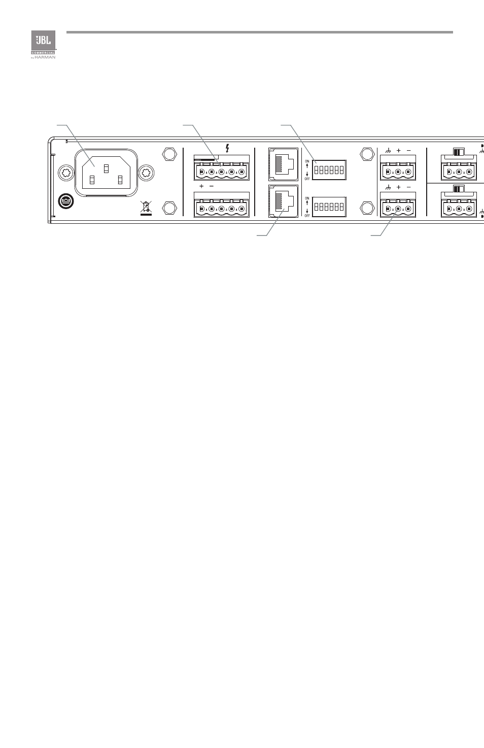
1.4 Rear Panel Controls and Connectors - Eight Channel
Figure 1.4 Rear View - CSMA 2120
5025056
100-240 V~ 50/60Hz 60W
CS
M
A 2
12
0
CSR-V
2
1
3 4 5 6
7 8 9 10 11 12
MIC
MONO SUM
MONO SUM
MONO SUM
AMP 1
AMP 2
AMP 1
AUX 1 OUT
CH4 INPUT
INPUT ROUTING
AUX 2 OUT
AMP 2
LINE
100V 70.7V COM
CH8 INPUT
CH3 INPUT
CH7 INPUT
CH2 INPUT
CH6 INPUT
CH1 INPUT
CH5 INPUT
PRIORITY
PRIORITY
MADE IN MALAYSIA
MIC
LINE
MIC
LINE
MIC
LINE
MIC
LINE
MIC
LINE
MIC
LINE
MIC
LINE
CAUTION - TO REDUCE THE RISK OF
ELECTRIC SHOCK, GROUNDING OF THE
CENTER PIN OF THE PLUG MUST BE
MAINTAINED.
1 - CH1 TO AMP2
2 - CH2 TO AMP2
3 - CH3 TO AMP2
4 - CH4 TO AMP2
5 - AMP1 Hi-Z
6 - PHANTOM
7 - CH5 TO AMP1
8 - CH6 TO AMP1
9 - CH7 TO AMP1
10 - CH8 TO AMP1
11 - AMP2 Hi-Z
12 - NC
CH 1 VOX
CH 5 VOX
MONO SUM
MONO SUM
MONO SUM
OUTPUTS
CLASS 2
WIRING
I
H
G
A
B
D
C
E
F
J
A. AC Power Inlet – Detachable IEC
B. Amplifier Output Connector – Outputs available for low impedance or
constant voltage systems.
C. Remote Volume Control – RJ45 style connector to connect to a JBL CSR-V
control module.
D. Dip switches for input routing, phantom power, and 70/100V operation
E. Aux Out – Auxiliary line level output connector for each output channel.