Crown Audio IQ-P.I.P.-MEM User Manual
Page 23
Page 23
Reference Manual
IQ–P.I.P.-MEM Programmable Input Processor for IQ Systems
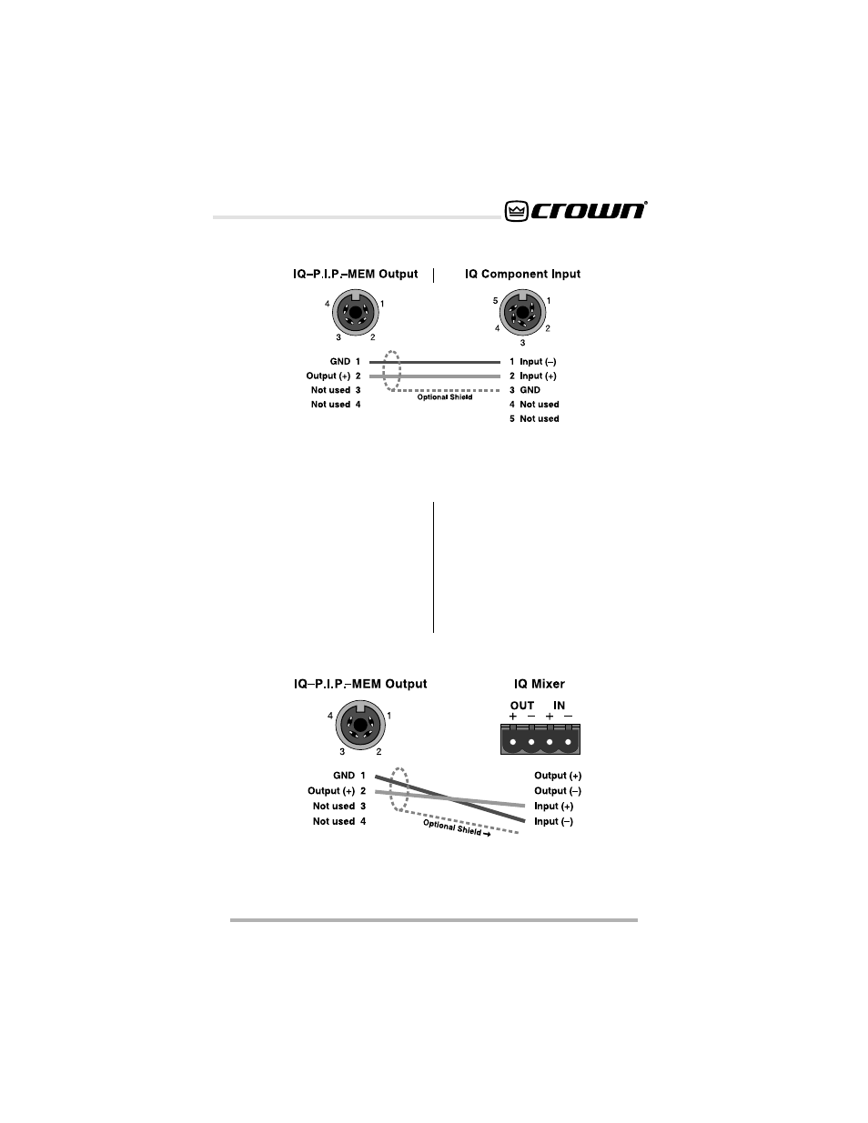
Figure 4.10 IQ–P.I.P.-MEM Output Connection to an IQ Component with a
Screw Terminal Plug Connector
The next four figures show how to
connect the IQ–P.I.P.-MEM to IQ
components with different connec-
tors. Figure 4.10 shows how the
Crown Bus output of the IQ–P.I.P.-
MEM should be connected to an IQ
component with a screw terminal
plug. Figure 4.11 shows how the
Crown Bus input of the IQ–P.I.P.-
MEM should be connected to a
component with a removable barrier
block connector. Figure 4.12 shows
how the Crown Bus output of the IQ–
P.I.P.-MEM should be connected to
an IQ component with an RJ45 con-
nector. Figure 4.13 shows how an IQ
component with an RJ45 connector
should be connected to the Crown Bus
input of the IQ-P.I.P.-MEM.
Figure 4.9 IQ–P.I.P.-MEM Output Connectionto Another IQ Component with
DIN Connectors