Installation prep, 3 installation, 1 setting the iq address – Crown Audio PSI User Manual
Page 8: 2 connecting to the crown bus
Page 8
IQ–PSI IQ Pocket Serial Interface
3 Installation
The installation of an
IQ–PSI
can be divided into four
parts: setting the IQ address, connecting to a Crown
Bus loop, connecting to a host computer and connect-
ing auxiliary devices.
3.1 Setting the IQ Address
Since more than one
IQ–PSI can be connected to the
same Crown Bus loop, it is necessary to give each unit a
unique IQ address. The IQ address is set with an 8-
segment DIP switch (SW3) located inside the battery
compartment.
Each segment of the DIP switch is, itself, a tiny switch
and has a numerical value which doubles as the seg-
ment number increases. For example, segment 1 has a
value of 1; segment 2 has a value of 2; segment 3 has a
value of 4; segment 4 has a value of 8; and so on.
The address is determined by adding the values of all
“ON” segments. In the example in Figure 3.2, segments
1, 3, 4 and 7 are on. Simply add the values to find the
address: 1+4+8+64=77.
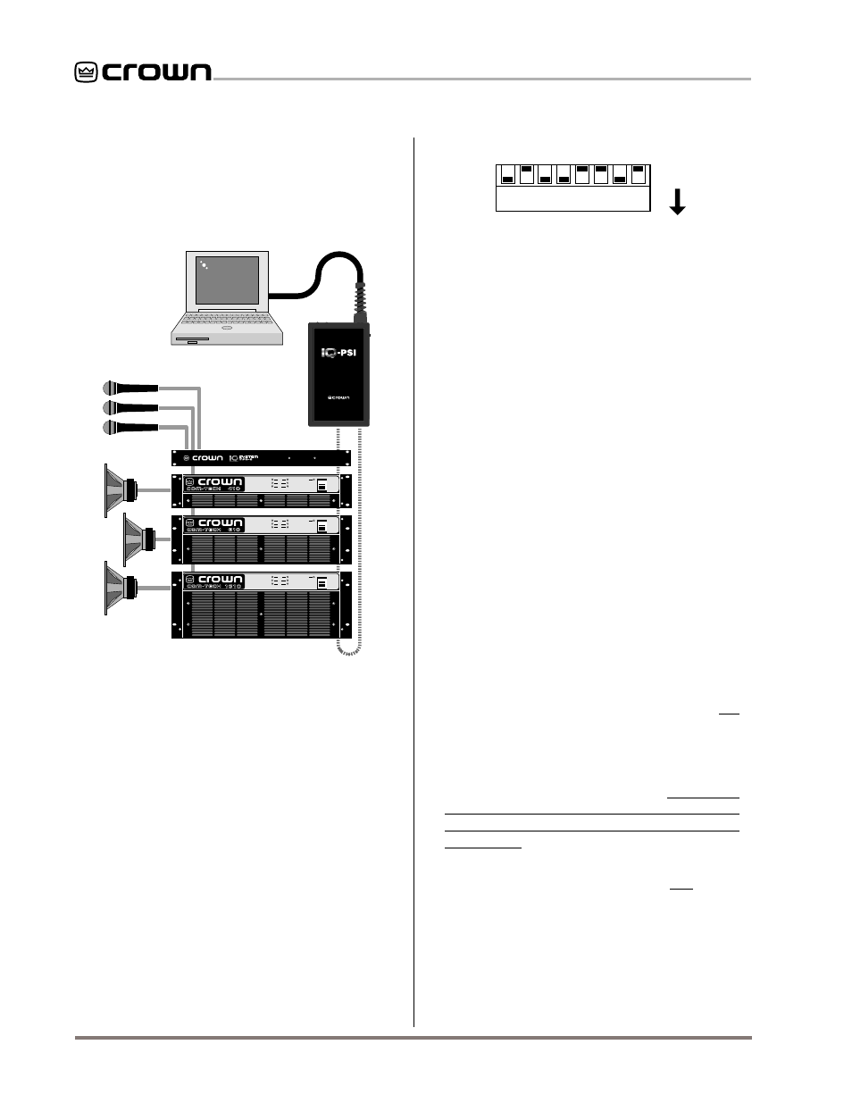
Fig. 3.1 An IQ System with an IQ–PSI
A valid IQ address is any number from 1 to 250. Do not
use a value higher than 250 since they are reserved for
special use. Also, an address of “0” (zero) should not be
used. A convenient series of IQ address tables are in-
cluded in Section 6 at the end of this manual.
3.2 Connecting to the Crown Bus
The Crown Bus is a serial communication loop designed
to transmit IQ commands and data. As a communica-
tion standard it is independent of the wiring system
used. This flexibility is a great strength, enabling a
Crown Bus loop to be wired with either fiber optic
cabling or with inexpensive twisted-pair wire, whichever
the installation requires. A single
IQ System
can have
more than one Crown Bus loop. To function properly, a
Crown Bus loop must be unbroken.
The Crown Bus is implemented in the
IQ–PSI
as a 20
milliamp current loop operating at 38.4 K baud, so that it
can function with inexpensive twisted-pair wiring. If fiber
optic wiring is required, contact Crown’s Technical Sup-
port Group at 1-800-342-6939 for information on adding
the appropriate transceivers.
Here are some guidelines for twisted-pair wiring:
•
When interference is a problem, use shielded
twisted-pair wire
at least 26 AWG in size. The wire
should be of good quality and should have low
capacitance—30 pF/foot or less is good. The
shield serves two purposes: First, it helps prevent
the IQ data signal from transmitting to nearby au-
dio wiring. Second, it helps prevent outside RF
from interfering with the data signal. However, in
most cases interference is not a problem and,
since unshielded wire has lower capacitance, it is a
better choice.
•
Minimize the total capacitance of a Crown Bus
loop.
The total capacitance should be less than 30
nF. Allow approximately 60 pF for each IQ compo-
nent in a loop. This accounts for a slight signal
degradation which occurs as data signals pass
through a component.
•
Add an IQ Repeater
for very long loops—greater
than 1,000 feet (305 m)—or when required by high-
capacitance wire. Although we recommend adding
ENABLE
DSPI
ENABLE
CH1
CH2
ODEP
POWER
OFF
IOC
SPI
ENABLE
CH1
CH2
ODEP
POWER
OFF
IOC
SPI
ENABLE
CH1
CH2
ODEP
POWER
OFF
IOC
SPI
CROWN BUS LOOP
RS232
AUX
CROWN BUS
10 VDC IN
1718 W. Mishawaka Rd.
Elkhart, IN 46517 U.S.A.
ENABLE
DSPI
RS232
POWER
P O C K E T S E R I A L I N T E R F A C E
1 2 3 4 5 6 7 8
1
2
4
8
16
32
64
128
ON
(DOWN)
Fig. 3.2 IQ Address Switch (SW3) Values