Technical info, 4 technical information – Crown Audio PSI User Manual
Page 12
Page 12
IQ–PSI IQ Pocket Serial Interface
4 Technical Information
The purpose of the
IQ–PSI is to provide a means for
the
IQ System host computer to communicate with the
IQ components on a Crown Bus loop. The pocket
serial interface allows for different baud rates from the
computer and uses the RS232 serial data standard.
(The baud rate can be set from 4,800 to 38,400.)
The
IQ-PSI functions as an interface when an active
computer is connected to the RS232 port. If a
computer is not present (or the computer is not on),
the
IQ-PSI will revert to the component mode.
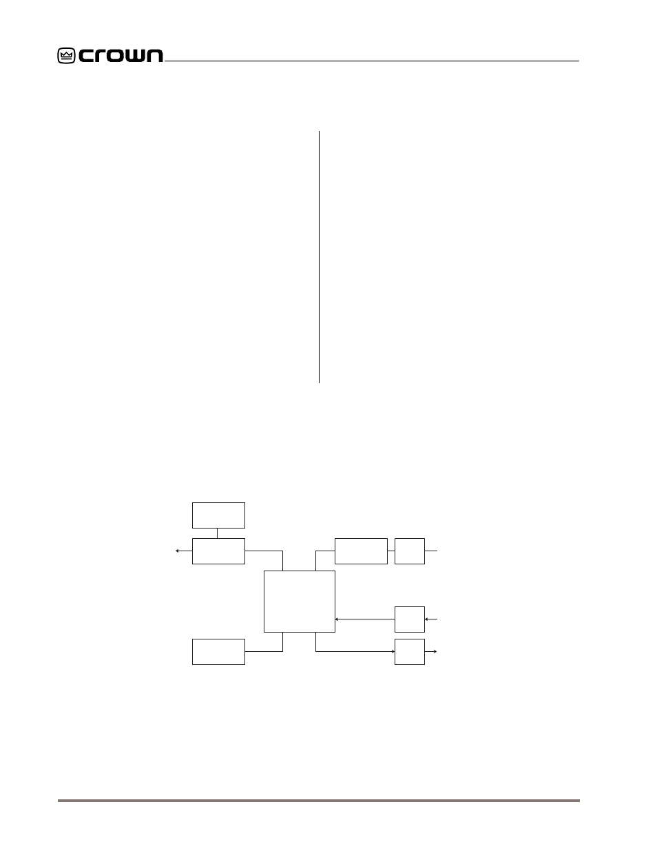
Figure 4.1 shows a block diagram of the
IQ–PSI. The
microprocessor of the interface communicates with
that of an IQ component over the 38,400 baud lines
originating from its own internal UART. It
communicates with a host computer via an external
UART.
Data from the host computer arrives at the serial
buffer at the user-selectable baud rate. The
IQ-PSI
receives the message and retransmits it, if necessary,
routing it to the appropriate component. If the
message received is intended for the IQ-PSI, the unit
takes appropriate action and responds with an
acknowledgment to the host.
Response and echo messages received from the IQ
loop are gathered at the loop input and sent out the
RS232 transmitter back to the host PC at the user-
determined baud rate.
The interface is also equipped with an auto reset
feature, generated by the microprocessor, which
provides both a reliable power-on reset and an
automatic “warm” reset in case control is lost due to a
noise pulse, etc.
An external +10 VDC power adapter is provided for
connection to a 120 VAC mains (North America only).
The unit can also operate for up to 1 hour with an
alkaline 9-volt battery.
RELAYS
OPTOCOUPLER
MICROPROCESSOR
BUFFER
BUFFER
BAUD RATE
GENERATOR
IQ ADDRESS
SWITCH
CROWN BUS
AUX
AUX
BAUD RATE
GENERATOR
BAUD RATE
GENERATOR
RS-232
Fig. 4.1 IQ–PSI Circuit Block Diagram